Toyota Tundra (2015 year). Manual - part 1295


  Index      Toyota     Toyota Tundra (2015 year) - Service and Repair Manual


Search            copyright infringement  


Content   ..  1293  1294  1295  1296   ..


Toyota Tundra (2015 year). Manual - part 1295


COMPONENT

OPERATION

Canister pump

module

Vents and closes EVAP system. When ECM turns valve ON, EVAP system closed. When ECM

turns valve OFF, EVAP system vented. Negative pressure (vacuum) created in EVAP system to

check for EVAP leaks by closing purge VSV, turning on vent valve (closed) and operating leak

detection pump (refer to fig. 1).

(b) Canister

pressure sensor

Indicates pressure as voltages. ECM supplies regulated 5 V to canister pressure sensor, and

uses feedback from sensor to monitor EVAP system pressure (refer to fig. 2).

(c) Leak detection

pump

Creates negative pressure (vacuum) in EVAP system for leak check.

(d) Reference

orifice

Has opening with 0.02-inch diameter. Vacuum produced through orifice by closing purge VSV,

turning off vent valve and operating leak detection pump to monitor reference pressure.
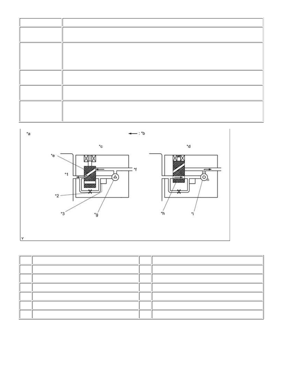
*1

Canister

*2

Reference Orifice (0.02 Inches)

*3

Canister Pressure Sensor

-

-

*a

Canister Pump Module (fig. 1)

*b

Airflow

*c

Condition: Purge Flow

*d

Condition: Leak Check

*e

Vent Valve: Off (Vent)

*f

to Canister Filter (Atmosphere)

*g

Leak Detection Pump: Off

*h

Vent Valve: on (closed)

*i

Leak Detection Pump: on

-

-

1UR-FE ENGINE CONTROL SYSTEM: SFI SYSTEM: EVAP System;...

WIRING DIAGRAM

1UR-FE ENGINE CONTROL SYSTEM: SFI SYSTEM: EVAP System;...

INSPECTION PROCEDURE

NOTICE:

The Techstream is required to conduct the following diagnostic troubleshooting procedure.

HINT:

Using the Techstream monitor results enables the EVAP (Evaporative Emission) system to be checked.
Read freeze frame data using the Techstream. Freeze frame data records the engine condition when
malfunctions are detected. When troubleshooting, freeze frame data can help determine if the vehicle was
moving or stationary, if the engine was warmed up or not, if the air-fuel ratio was lean or rich, and other
data from the time the malfunction occurred.

PROCEDURE

1UR-FE ENGINE CONTROL SYSTEM: SFI SYSTEM: EVAP System;...

1.

CONFIRM DTC

(a) Turn the ignition switch off and wait for 10 seconds.

(b) Turn the ignition switch to ON.

(c) Turn the ignition switch off and wait for 10 seconds.

(d) Connect the Techstream to the DLC3.

(e) Turn the ignition switch to ON and turn the Techstream on.

(f) Enter the following menus: Powertrain / Engine and ECT / Trouble Codes.

(g) Confirm DTCs and freeze frame data.

If any EVAP system DTCs are stored, the malfunctioning area can be determined using the table below.

NOTICE:

If the reference pressure difference between the first and second checks is greater than the specification, all

1UR-FE ENGINE CONTROL SYSTEM: SFI SYSTEM: EVAP System;...


Content   ..  1293  1294  1295  1296   ..