Content .. 1292 1293 1294 1295 ..
Toyota Tundra (2015 year). Manual - part 1294
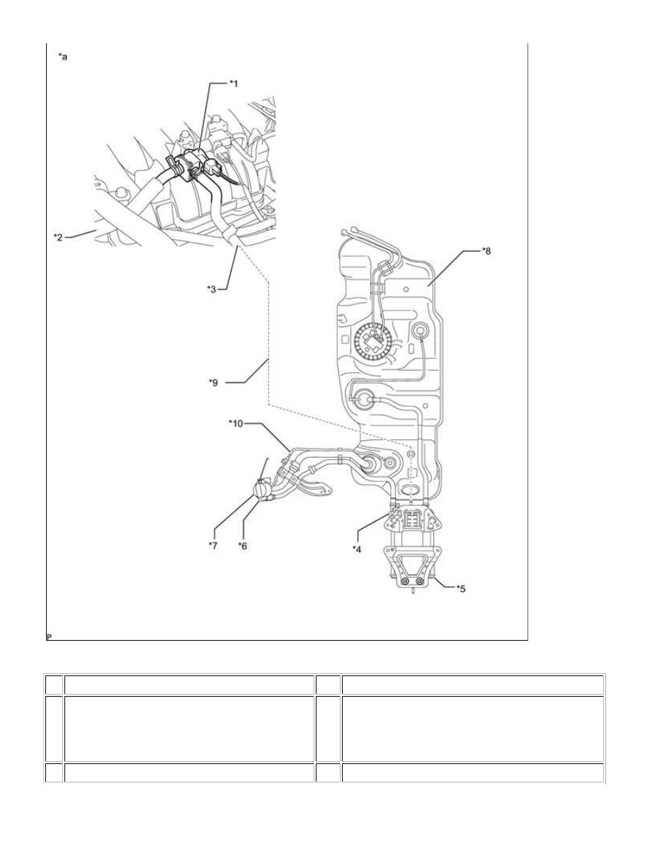
Text in Illustration
*1 Purge VSV
*2
Purge Line Hose (to Intake Manifold)
*3 Purge Line Hose (from Canister)
*4
Canister Pump Module
- Canister Pressure Sensor
- Leak Detection Pump
- Vent Valve
*5 Canister Assembly
*6
Fuel Tank Inlet Pipe Sub-assembly (Canister Filter)
1UR-FE ENGINE CONTROL SYSTEM: SFI SYSTEM: EVAP System;...