Content .. 1213 1214 1215 1216 ..
Toyota Tundra (2015 year). Manual - part 1215
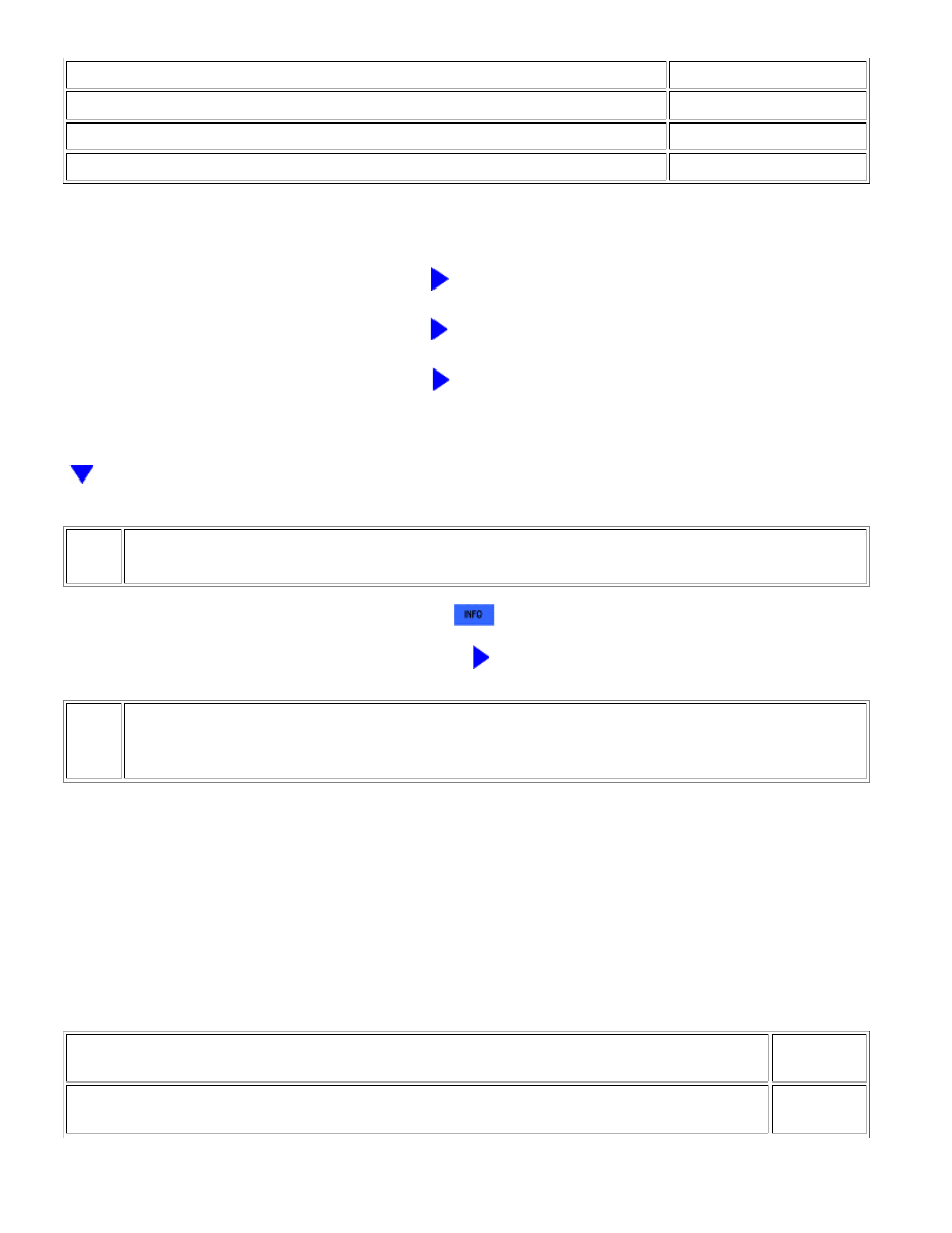
A
RESULT
PROCEED TO
P106B is output
B
P106A and P106B are output
C
P106A, P106B and other DTCs are output
D
HINT:
If any DTCs other than P106A or P106B are output, perform troubleshooting for those DTCs first.
B
GO TO STEP 3
C
GO TO STEP 6
D
GO TO DTC CHART
2.
REPLACE MANIFOLD ABSOLUTE PRESSURE SENSOR
(a) Replace the manifold absolute pressure sensor
.
NEXT
GO TO STEP 7
3.
READ VALUE USING TECHSTREAM (AIR PUMP PRESSURE (ABSOLUTE) AND AIR PUMP2
PRESSURE (ABSOLUTE))
(a) Connect the Techstream to the DLC3.
(b) Turn the ignition switch to ON.
(c) Turn the Techstream on.
(d) Enter the following menus: Powertrain / Engine and ECT / Data List / Air Pump Pressure (Absolute),
Air Pump2 Pressure (Absolute) and Vapor Pressure Pump.
(e) Read the value.
Result
RESULT
PROCEED
TO
Difference between Air Pump Pressure (Absolute) and Vapor Pressure Pump is more than 3.5 kPa
(26 mmHg)
A
1UR-FE ENGINE CONTROL SYSTEM: SFI SYSTEM: P106A,P106B...