Toyota Tundra (2015 year). Manual - part 1209


  Index      Toyota     Toyota Tundra (2015 year) - Service and Repair Manual


Search            copyright infringement  


Content   ..  1207  1208  1209  1210   ..


Toyota Tundra (2015 year). Manual - part 1209


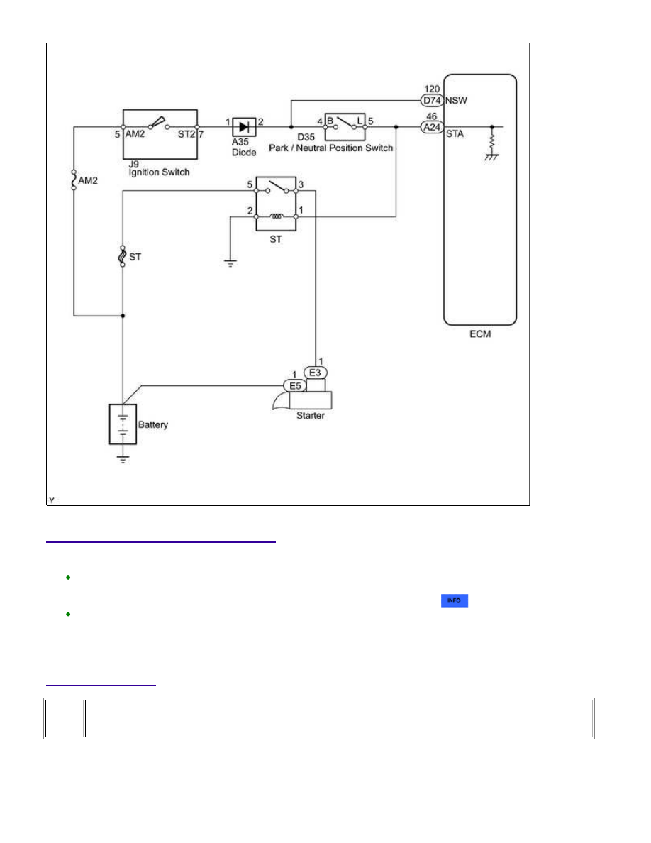
INSPECTION PROCEDURE

HINT:

The following troubleshooting flowchart is based on the premise that the engine can be cranked normally.

If the engine will not crank, proceed to the Problem Symptoms Table 


.

Read freeze frame data using the Techstream. Freeze frame data records the engine condition when
malfunctions are detected. When troubleshooting, freeze frame data can help determine if the vehicle was
moving or stationary, if the engine was warmed up or not, if the air-fuel ratio was lean or rich, and other
data from the time the malfunction occurred.

PROCEDURE

1.

READ VALUE USING TECHSTREAM (STARTER SIGNAL)

(a) Connect the Techstream to the DLC3.

(b) Turn the ignition switch to ON.

1UR-FE ENGINE CONTROL SYSTEM: SFI SYSTEM: P0617; Starter...

A

(c) Turn the Techstream on.

(d) Enter the following menus: Powertrain / Engine and ECT / Data List / Starter Signal.

(e) Check the value displayed on the Techstream when the ignition switch is turned to the ON and

START positions.

OK:

IGNITION SWITCH POSITION

STARTER SIGNAL

ON

OFF

START

ON

NG

GO TO STEP 2

OK

CHECK FOR INTERMITTENT PROBLEMS

2.

READ VALUE USING TECHSTREAM (STARTER SIGNAL)

(a) Disconnect the Park/Neutral Position (PNP) switch connector.

(b) Connect the Techstream to the DLC3.

(c) Turn the ignition switch to ON.

(d) Turn the Techstream on.

(e) Enter the following menus: Powertrain / Engine and ECT / Data List / Starter Signal.

(f) Check the value displayed on the Techstream when the ignition switch is turned to the ON and START

positions.

Result

STARTER SIGNAL

PROCEED TO

Remains ON

A

OFF

B

B

GO TO STEP 4

3.

INSPECT ECM (STA TERMINAL VOLTAGE)

(a) Disconnect the ECM connector.

1UR-FE ENGINE CONTROL SYSTEM: SFI SYSTEM: P0617; Starter...

A

(b) Disconnect the PNP switch connector.

(c) Turn the ignition switch to ON.

(d) Measure the voltage according to the value(s) in the table below.

Standard Voltage:

TESTER CONNECTION

CONDITION

SPECIFIED CONDITION

PROCEED TO

A24-46 (STA) - Body ground

Ignition switch ON

Below 1.5 V

A

11 to 14 V

B

B

REPAIR OR REPLACE HARNESS OR CONNECTOR

(ECM - PNP SWITCH - ST RELAY)

A

REPLACE ECM

4.

INSPECT PARK/NEUTRAL POSITION SWITCH ASSEMBLY

(a) Disconnect the PNP switch connector.

(b) Measure the resistance according to the value(s) in the table

below.

Standard Resistance:

TESTER CONNECTION

CONDITION

SPECIFIED CONDITION

4 (B) - 5 (L)

Except P or N

10 kΩ or higher

2 (RB) - 5 (L)

All positions

10 kΩ or higher

Result

RESULT

PROCEED TO

Short between 4 and 5

A

Short between 2 and 5

B

Within standard range

C

B

REPLACE PARK/NEUTRAL POSITION SWITCH

ASSEMBLY

C

GO TO STEP 6

1UR-FE ENGINE CONTROL SYSTEM: SFI SYSTEM: P0617; Starter...

NEXT

OK

5.

REPLACE PARK/NEUTRAL POSITION SWITCH ASSEMBLY

(a) Replace the park/neutral position switch.

for 2WD 

for 4WD 

6.

INSPECT IGNITION SWITCH ASSEMBLY

(a) Disconnect the ignition switch assembly connector.

(b) Measure the resistance according to the value(s) in the table

below.

Standard Resistance:

TESTER

CONNECTION

SWITCH CONDITION

SPECIFIED

CONDITION

5 (AM2) - 7 (ST2)

Ignition switch position not

START

10 kΩ or higher

Ignition switch position

START

Below 1 Ω

NG

REPLACE IGNITION SWITCH ASSEMBLY

7.

READ VALUE USING TECHSTREAM (STARTER SIGNAL)

(a) Connect the Techstream to the DLC3.

(b) Turn the ignition switch to ON.

(c) Turn the Techstream on.

1UR-FE ENGINE CONTROL SYSTEM: SFI SYSTEM: P0617; Starter...


Content   ..  1207  1208  1209  1210   ..