Toyota Tundra (2015 year). Manual - part 1200


  Index      Toyota     Toyota Tundra (2015 year) - Service and Repair Manual


Search            copyright infringement  


Content   ..  1198  1199  1200  1201   ..


Toyota Tundra (2015 year). Manual - part 1200


OK

If other DTCs relating to different systems that have terminal E2 as the ground terminal are output
simultaneously, terminal E2 may have an open circuit.
Read freeze frame data using the Techstream. Freeze frame data records the engine condition when
malfunctions are detected. When troubleshooting, freeze frame data can help determine if the vehicle was
moving or stationary, if the engine was warmed up or not, if the air-fuel ratio was lean or rich, and other
data from the time the malfunction occurred.

PROCEDURE

1.

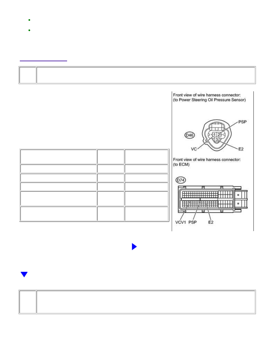
CHECK HARNESS AND CONNECTOR (ECM - POWER STEERING OIL PRESSURE SENSOR)

(a) Disconnect the ECM connector.

(b) Disconnect the power steering oil pressure sensor connector.

(c) Measure the resistance according to the value(s) in the table

below.

Standard Resistance:

TESTER CONNECTION

CONDITION

SPECIFIED

CONDITION

D46-2 (PSP) - D74-72 (PSP)

Always

Below 1 Ω

D46-1 (VC) - D74-67 (VCV1)

Always

Below 1 Ω

D46-3 (E2) - D74-98 (E2)

Always

Below 1 Ω

D46-2 (PSP) or D74-72 (PSP) -

Body ground

Always

10 kΩ or higher

D46-1 (VC) or D74-67 (VCV1) -

Body ground

Always

10 kΩ or higher

NG

REPAIR OR REPLACE HARNESS OR CONNECTOR

2.

CHECK TERMINAL VOLTAGE (POWER SOURCE OF POWER STEERING OIL PRESSURE
SENSOR)

(a) Disconnect the power steering oil pressure sensor connector.

(b) Turn the ignition switch to ON.

1UR-FE ENGINE CONTROL SYSTEM: SFI SYSTEM: P0550,P0552,...

OK

NEXT

(c) Measure the voltage according to the value(s) in the table below.

Standard Voltage:

TESTER CONNECTION

SWITCH CONDITION

SPECIFIED CONDITION

D46-2 (PSP) - D46-3 (E2)

Ignition switch ON

4.5 to 5.5 V

NG

REPLACE ECM

3.

REPLACE POWER STEERING OIL PRESSURE SENSOR

(a) Replace the power steering oil pressure sensor 


.

4.

CONFIRM WHETHER DTC OUTPUT RECURS

(a) Connect the Techstream to the DLC3.

(b) Turn the ignition switch to ON.

(c) Turn the Techstream on.

(d) Drive the vehicle in accordance with the driving pattern described in the Confirmation Driving

Pattern.

(e) Enter the following menus: Powertrain / Engine and ECT / Trouble Codes.

(f) Confirm that the DTC is not output

NEXT

END

1UR-FE ENGINE CONTROL SYSTEM: SFI SYSTEM: P0550,P0552,...

Last Modified: 9-16-2014

6.6 C

Doc ID: RM000000T8P1F3X

Model Year: 2015

Model: Tundra

Prod Date Range: [08/2014 -           ]

Title: 1UR-FE ENGINE CONTROL SYSTEM: SFI SYSTEM: P0560; System Voltage; 2015 MY Tundra [08/2014 -

       ]

DTC

P0560

System Voltage

DESCRIPTION

The battery supplies electricity to the ECM even when the ignition switch is off. This power allows the ECM to

store data such as DTC history, freeze frame data and fuel trim values. If the battery voltage falls below a

minimum level, the memory is cleared and the ECM determines that there is a malfunction in the power supply

circuit. When the engine is next started, the ECM illuminates the MIL and stores the DTC.

DTC NO.

DTC DETECTION CONDITION

TROUBLE AREA

P0560

Open in ECM back up power source circuit

(1 trip detection logic)

Open in back up power source circuit

Battery

Battery terminals

EFI NO. 1 fuse

ECM

HINT:

If DTC P0560 is stored, the ECM does not store other DTCs or the data stored in the ECM is partly cleared.

MONITOR STRATEGY

Related DTCs

P0560: ECM system voltage

Required Sensors/Components (Main)

ECM

Required Sensors/Components (Related)

-

Duration

3 seconds

MIL Operation

Immediate (MIL illuminated after next engine start)

TYPICAL ENABLING CONDITIONS

Monitor runs whenever following DTCs not present

None

TYPICAL MALFUNCTION THRESHOLDS

Stand-by RAM

Initialized

ECM power source

Less than 3.5 V

1UR-FE ENGINE CONTROL SYSTEM: SFI SYSTEM: P0560; Syste...

CONFIRMATION DRIVING PATTERN

Connect the Techstream to the DLC3.

1. 

Turn the ignition switch to ON and turn the Techstream on.

2. 

Clear DTCs (even if no DTCs are stored, perform the clear DTC operation).

3. 

Turn the ignition switch off and wait for at least 30 seconds.

4. 

Turn the ignition switch to ON and turn the Techstream on.

5. 

Wait 5 seconds or more.

6. 

Enter the following menus: Powertrain / Engine and ECT / Trouble Codes.

7. 

Read the pending DTCs.

HINT:

If a pending DTC is output, the system is malfunctioning.
If a pending DTC is not output, perform the following procedure.

8. 

Enter the following menus: Powertrain / Engine and ECT / Utility / All Readiness.

9. 

Input the DTC: P0560.

10. 

Check the DTC judgment result.

TESTER

DISPLAY

DESCRIPTION

NORMAL

DTC judgment completed

System normal

ABNORMAL

DTC judgment completed

System abnormal

INCOMPLETE

DTC judgment not completed

Perform driving pattern after confirming DTC enabling conditions

N/A

Unable to perform DTC judgment

HINT:

If the judgment result shows ABNORMAL, the system has a malfunction.

11. 

If the test result is INCOMPLETE or N/A and no pending DTC is output, perform a universal trip and

check for permanent DTCs 


.

HINT:

If a permanent DTC is output, the system is malfunctioning.
If no permanent DTC is output, the system is normal.

12. 

WIRING DIAGRAM

1UR-FE ENGINE CONTROL SYSTEM: SFI SYSTEM: P0560; Syste...


Content   ..  1198  1199  1200  1201   ..