Content .. 1186 1187 1188 1189 ..
Toyota Tundra (2015 year). Manual - part 1188
GO TO STEP 6
OK
REPLACE ECM
6.
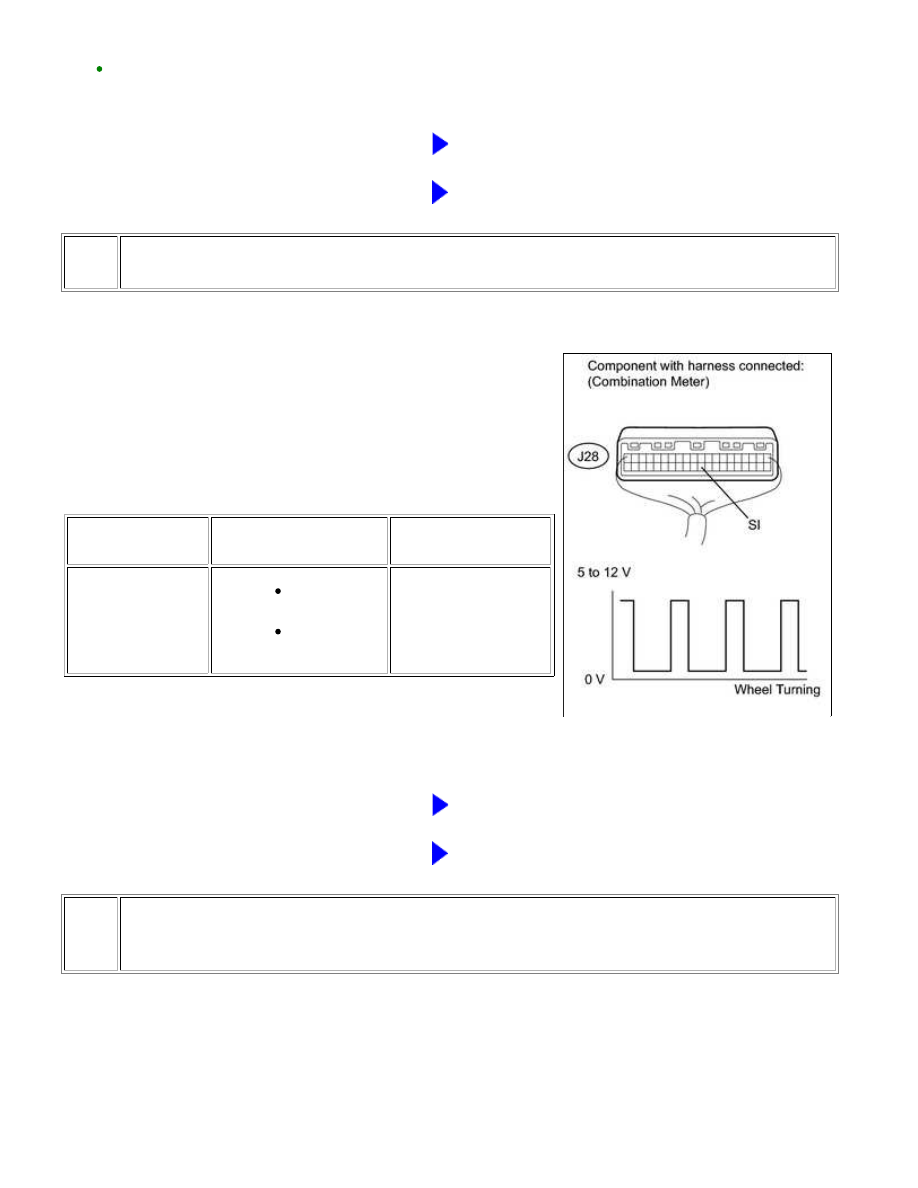
INSPECT COMBINATION METER ASSEMBLY (SPD SIGNAL INPUT WAVEFORM)
(a) Move the shift lever to the neutral position.
(b) Jack up the vehicle.
(c) Turn the ignition switch to ON.
(d) Measure the voltage according to the value(s) in the table
below.
Standard voltage:
TESTER
CONNECTION
SWITCH CONDITION
SPECIFIED
CONDITION
J28-30 (SI) - Body
ground
Ignition switch
ON
Wheel is
turned slowly
Voltage generated
intermittently
HINT:
The output voltage should fluctuate up and down, similarly to the
diagram, when the wheel is turned slowly.
NG
GO TO STEP 7
OK
REPLACE COMBINATION METER ASSEMBLY
7.
CHECK HARNESS AND CONNECTOR (COMBINATION METER - VSC ACTUATOR
ASSEMBLY)
1UR-FE ENGINE CONTROL SYSTEM: SFI SYSTEM: P0500; Vehicl...