Toyota Tundra (2015 year). Manual - part 1172


  Index      Toyota     Toyota Tundra (2015 year) - Service and Repair Manual


Search            copyright infringement  


Content   ..  1170  1171  1172  1173   ..


Toyota Tundra (2015 year). Manual - part 1172


INSPECTION PROCEDURE

HINT:

By using the Techstream to perform the Secondary Air Injection Check operation in the System Check, the
air-fuel ratio and the pressure in the secondary air injection system passage can be checked while the
secondary air injection system is operating. This helps technicians to troubleshoot the system when it
malfunctions.
Read freeze frame data using the Techstream. Freeze frame data records the engine condition when
malfunctions are detected. When troubleshooting, freeze frame data can help determine if the vehicle was
moving or stationary, if the engine was warmed up or not, if the air-fuel ratio was lean or rich, and other
data from the time the malfunction occurred.
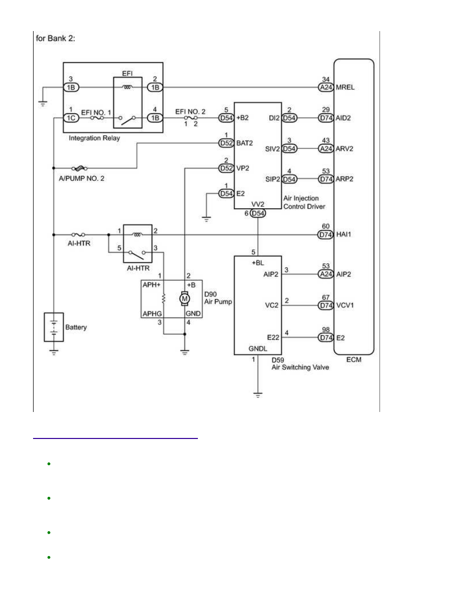
Bank 1 refers to the bank that includes the No. 1 cylinder*.

*: The No. 1 cylinder is the cylinder which is farthest from the transmission.

Bank 2 refers to the bank that does not include the No. 1 cylinder.

1UR-FE ENGINE CONTROL SYSTEM: SFI SYSTEM: P0412,P0415; ...

A

PROCEDURE

1.

INSPECT AIR SWITCHING VALVE ASSEMBLY

(a) Inspect the air switching valve (for bank 1) 


.

(b) Inspect the air switching valve (for bank 2) 


.

Result

RESULT

PROCEED TO

OK

A

NG (for Bank 1)

B

NG (for Bank 2)

C

B

REPLACE AIR SWITCHING VALVE ASSEMBLY (FOR

BANK 1)

C

REPLACE AIR SWITCHING VALVE ASSEMBLY (FOR

BANK 2)

2.

CHECK HARNESS AND CONNECTOR (AIR SWITCHING VALVE - BODY GROUND)

(a) Disconnect the air switching valve connector.

(b) Measure the resistance according to the value(s) in the table

below.

Standard Resistance:

TESTER CONNECTION

CONDITION

SPECIFIED CONDITION

D58-1 (GND) - Body ground

Always

Below 1 Ω

D59-1 (GNDL) - Body ground

Always

Below 1 Ω

NG

REPAIR OR REPLACE HARNESS OR CONNECTOR

1UR-FE ENGINE CONTROL SYSTEM: SFI SYSTEM: P0412,P0415; ...

OK

3.

CHECK HARNESS AND CONNECTOR (AIR SWITCHING VALVE - AIR INJECTION
CONTROL DRIVER)

(a) Disconnect the air switching valve connector.

(b) Disconnect the air injection control driver connector.

(c) Measure the resistance according to the value(s) in the table

below.

Standard Resistance:

TESTER CONNECTION

CONDITION

SPECIFIED

CONDITION

D58-5 (+B) - D50-6 (VV)

Always

Below 1 Ω

D59-5 (+BL) - D54-6 (VV2)

Always

Below 1 Ω

D58-5 (+B) or D50-6 (VV) - Body

ground

Always

10 kΩ or higher

D59-5 (+BL) or D54-6 (VV2) -

Body ground

Always

10 kΩ or higher

NG

REPAIR OR REPLACE HARNESS OR CONNECTOR

OK

REPLACE AIR INJECTION CONTROL DRIVER (FOR

BANK 1 OR BANK 2)

1UR-FE ENGINE CONTROL SYSTEM: SFI SYSTEM: P0412,P0415; ...

Last Modified: 9-16-2014

6.6 C

Doc ID: RM0000012FZ05UX

Model Year: 2015

Model: Tundra

Prod Date Range: [08/2014 -           ]

Title: 1UR-FE ENGINE CONTROL SYSTEM: SFI SYSTEM: P0418,P0419; Secondary Air Injection System Control

"A" Circuit; 2015 MY Tundra [08/2014 -        ]

DTC

P0418

Secondary Air Injection System Control "A" Circuit

DTC

P0419

Secondary Air Injection System Relay "B" Circuit

DESCRIPTION

Refer to DTC P0412 


.

DTC

NO.

DTC DETECTION CONDITION

TROUBLE AREA

P0418

P0419

Secondary Air Injection (AIR) system not

operating (air pump OFF, Air Switching

Valve [ASV] OFF)

a. 

Diagnostic signal from Air Injection Control

Driver (AID) 20%

b. 

Battery voltage 8 V or more

c. 

Open in air injection control

driver circuit

Air pump

Air injection control driver

ECM

P0418

P0419

Secondary Air Injection (AIR) system

operating (air pump ON, Air Switching Valve

[ASV] ON)

a. 

Diagnostic signal from Air Injection Control

Driver (AID) 20%

b. 

Battery voltage 8 V or more

c. 

Short between air injection

control driver circuit and body

ground

Air pump

Air injection control driver

ECM

MONITOR DESCRIPTION

to the ECM.

For a short time after a cold engine start, the ECM transmits command signals to the AID to drive the air pump

and ASV.

signals from the ECM to drive the air pump.

1UR-FE ENGINE CONTROL SYSTEM: SFI SYSTEM: P0418,P0419; ...


Content   ..  1170  1171  1172  1173   ..