Toyota Tundra (2015 year). Manual - part 1173


  Index      Toyota     Toyota Tundra (2015 year) - Service and Repair Manual


Search            copyright infringement  


Content   ..  1171  1172  1173  1174   ..


Toyota Tundra (2015 year). Manual - part 1173


The voltage at the AID terminal relating to the air pump is high despite the AID receiving no command

signals from the ECM to drive the air pump.

The ECM stores the DTC based on diagnostic signals from the AID.
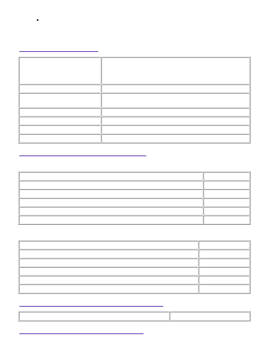
MONITOR STRATEGY

Related DTCs

P0418: Secondary air injection system air pump circuit range check

(Bank 1)

P0419: Secondary air injection system air pump circuit range check

(Bank 2)

Required Sensors/Components (Main)

Air injection control driver

Required Sensors/Components

(Related)

Air pump

Duration

3 seconds

MIL Operation

2 driving cycles

TYPICAL ENABLING CONDITIONS

Case 1

Monitor runs whenever following DTCs not present

None

Secondary air injection pump

Operating

Secondary air injection switching valve

Operating

Battery voltage

8 V or more

Ignition switch

ON

Starter

OFF

Case 2

Monitor runs whenever following DTCs not present

None

Secondary air injection pump

Not operating

Secondary air injection switching valve

Not operating

Battery voltage

8 V or more

Ignition switch

ON

Starter

OFF

TYPICAL MALFUNCTION THRESHOLDS

Diagnostic signal duty ratio from air injection control driver

11% or more, and 29% or less

COMPONENT OPERATING RANGE

1UR-FE ENGINE CONTROL SYSTEM: SFI SYSTEM: P0418,P0419; ...

Diagnostic signal duty ratio from air injection

control driver

70% or more, and 90% or less when secondary air injection

system operating.

0% when secondary air injection system not operating.

CONFIRMATION DRIVING PATTERN

NOTICE:

prohibition (WAIT or ERROR).

If ERROR is displayed on the Techstream during the test, stop the engine for 10 minutes, and then

try again.

1. 

Turn the ignition switch off.

2. 

Connect the Techstream to the DLC3.

3. 

Turn the ignition switch to ON.

4. 

Turn the Techstream on.

5. 

Clear DTCs (if set) 


.

6. 

Turn the ignition switch off and wait for at least 30 seconds.

7. 

Turn the ignition switch to ON and turn the Techstream on.

8. 

Enter the following menus: Powertrain / Engine and ECT / Utility / Secondary Air Injection Check /

Automatic Mode.

9. 

Start the engine after the Techstream initialization is finished.

10. 

Perform the System Check operation by pressing ENTER (Next).

11. 

Perform the following to confirm the AIR system pending codes: Press ENTER (Exit).

12. 

Check for pending DTCs.

OK:

No pending DTC is output.

13. 

After the "Secondary air injection check" is completed, check for All Readiness by entering the

following menus: Powertrain / Engine and ECT / Utility / All Readiness.

14. 

Input the DTC: P0418 or P0419.

15. 

Check the DTC judgment result.

TESTER

DISPLAY

DESCRIPTION

NORMAL

DTC judgment completed

System normal

ABNORMAL

DTC judgment completed

System abnormal

16. 

1UR-FE ENGINE CONTROL SYSTEM: SFI SYSTEM: P0418,P0419; ...

TESTER

DISPLAY

DESCRIPTION

INCOMPLETE

DTC judgment not completed

Perform driving pattern after confirming DTC enabling conditions

N/A

Unable to perform DTC judgment

HINT:

If the judgment result shows NORMAL, the system is normal.
If the judgment result shows ABNORMAL, the system has a malfunction.

If the test result is INCOMPLETE or N/A and no pending DTC is output, perform a universal trip and

check for permanent DTCs 


.

HINT:

If no permanent DTC is output, the system is normal.
If a permanent DTC is output, the system is malfunctioning.

17. 

Turn the ignition switch off.

18. 

WIRING DIAGRAM

Refer to DTC P0412 


.

INSPECTION PROCEDURE

HINT:

By using the Techstream to perform the Secondary Air Injection Check operation in the System Check, the
air-fuel ratio and the pressure in the secondary air injection system passage can be checked while the
secondary air injection system is operating. This helps technicians to troubleshoot the system when it
malfunctions.
Read freeze frame data using the Techstream. Freeze frame data records the engine condition when
malfunctions are detected. When troubleshooting, freeze frame data can help determine if the vehicle was
moving or stationary, if the engine was warmed up or not, if the air-fuel ratio was lean or rich, and other
data from the time the malfunction occurred.
Bank 1 refers to the bank that includes the No. 1 cylinder*.

*: The No. 1 cylinder is the cylinder which is farthest from the transmission.

Bank 2 refers to the bank that does not include the No. 1 cylinder.

PROCEDURE

1.

CHECK HARNESS AND CONNECTOR (AIR PUMP - AIR INJECTION CONTROL DRIVER,
BODY GROUND)

1UR-FE ENGINE CONTROL SYSTEM: SFI SYSTEM: P0418,P0419; ...

OK

(a) Disconnect the cable from the battery negative (-) terminal.

(b) Disconnect the cable from the battery positive (+) terminal.

(c) Disconnect the air pump connector.

(d) Disconnect the air injection control driver (AID) connector.

(e) Measure the resistance according to the value(s) in the table

below.

Standard Resistance:

TESTER CONNECTION

CONDITION

SPECIFIED

CONDITION

D89-2 (B) - D48-2 (VP)

Always

Below 1 Ω

D90-2 (+B) - D52-2 (VP2)

Always

Below 1 Ω

D48-1 (BATT) - Battery positive (+)

terminal

Always

Below 1 Ω

D52-1 (BAT2) - Battery positive (+)

terminal

Always

Below 1 Ω

D89-4 (E) - Body ground

Always

Below 1 Ω

D90-4 (GND) - Body ground

Always

Below 1 Ω

D89-2 (B) or D48-2 (VP) - Body

ground

Always

10 kΩ or higher

D90-2 (+B) or D52-2 (VP2) - Body

ground

Always

10 kΩ or higher

D48-1 (BATT) or Battery positive (+)

terminal - Body ground

Always

10 kΩ or higher

D52-1 (BAT2) or Battery positive (+)

terminal - Body ground

Always

10 kΩ or higher

NG

REPAIR OR REPLACE HARNESS OR CONNECTOR

2.

CHECK AIR PUMP

1UR-FE ENGINE CONTROL SYSTEM: SFI SYSTEM: P0418,P0419; ...


Content   ..  1171  1172  1173  1174   ..