Toyota Tundra (2015 year). Manual - part 1131


  Index      Toyota     Toyota Tundra (2015 year) - Service and Repair Manual


Search            copyright infringement  


Content   ..  1129  1130  1131  1132   ..


Toyota Tundra (2015 year). Manual - part 1131


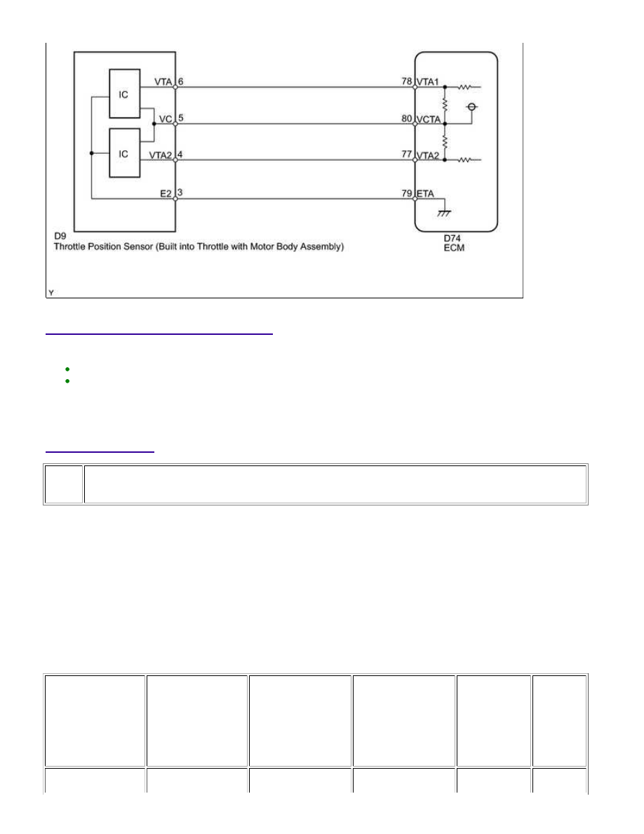
INSPECTION PROCEDURE

HINT:

These DTCs relate to the Throttle Position (TP) sensor.
Read freeze frame data using the Techstream. Freeze frame data records the engine condition when
malfunctions are detected. When troubleshooting, freeze frame data can help determine if the vehicle was
moving or stationary, if the engine was warmed up or not, if the air-fuel ratio was lean or rich, and other
data from the time the malfunction occurred.

PROCEDURE

1.

READ VALUE USING TECHSTREAM (THROTTLE POSITION)

(a) Connect the Techstream to the DLC3.

(b) Turn the ignition switch to ON.

(c) Turn the Techstream on.

(d) Enter the following menus: Powertrain / Engine and ECT / Data List / Throttle Position No. 1 and

Throttle Position No. 2.

(e) Check the values displayed on the Techstream.

Result

THROTTLE

POSITION NO. 1

(VTA1)

WHEN

ACCELERATOR

PEDAL RELEASED

THROTTLE

POSITION NO. 2

(VTA2)

WHEN

ACCELERATOR

PEDAL RELEASED

THROTTLE

POSITION NO. 1

(VTA1)

WHEN

ACCELERATOR

PEDAL DEPRESSED

THROTTLE

POSITION NO. 2

(VTA2)

WHEN

ACCELERATOR

PEDAL DEPRESSED

TROUBLE

AREA

PROCEED

TO

0 to 0.2 V

0 to 0.2 V

0 to 0.2 V

0 to 0.2 V

VC circuit

A

1UR-FE ENGINE CONTROL SYSTEM: SFI SYSTEM: P0120-P0123,...

A

THROTTLE

POSITION NO. 1

(VTA1)

WHEN

ACCELERATOR

PEDAL RELEASED

THROTTLE

POSITION NO. 2

(VTA2)

WHEN

ACCELERATOR

PEDAL RELEASED

THROTTLE

POSITION NO. 1

(VTA1)

WHEN

ACCELERATOR

PEDAL DEPRESSED

THROTTLE

POSITION NO. 2

(VTA2)

WHEN

ACCELERATOR

PEDAL DEPRESSED

TROUBLE

AREA

PROCEED

TO

open

4.5 to 4.98 V

4.5 to 4.98 V

4.5 to 4.98 V

4.5 to 4.98 V

E2 circuit

open

A

0 to 0.2 V,

or 4.5 to 4.98 V

2.1 to 3.1 V

(Fail-safe)

0 to 0.2 V,

or 4.5 to 4.98 V

2.1 to 3.1 V

(Fail-safe)

VTA1 circuit

open or

ground short

A

0.6 to 1.4 V

(Fail-safe)

0 to 0.2 V,

or 4.5 to 4.98 V

0.6 to 1.4 V

(Fail-safe)

0 to 0.2 V,

or 4.5 to 4.98 V

VTA2 circuit

open or

ground short

A

0.5 to 1.1 V

2.1 to 3.1 V

3.2 to 4.8 V

(Not fail-safe)

4.6 to 4.98 V

(Not fail-safe)

TP sensor

circuit normal

B

HINT:

DTC P0121 is stored when the VTA1 and VTA2 output voltages are not consistent with the sensor
characteristics. Therefore, check the freeze frame data when this DTC is stored. Use the following formula
to confirm the relative differences in voltage.

Characteristic Sensor Output:
VTA2 x 0.8 is approximately equal to VTA1 + 1.11 V

VTA1: Throttle Position No. 1

VTA2: Throttle Position No. 2

If DTC P0121 is output, proceed to "CHECK HARNESS AND CONNECTOR (THROTTLE POSITION SENSOR -
ECM)".

B

GO TO STEP 5

2.

CHECK HARNESS AND CONNECTOR (THROTTLE POSITION SENSOR - ECM)

1UR-FE ENGINE CONTROL SYSTEM: SFI SYSTEM: P0120-P0123,...

OK

(a) Disconnect the throttle with motor body assembly connector.

(b) Disconnect the ECM connector.

(c) Measure the resistance according to the value(s) in the table

below.

Standard Resistance:

TESTER CONNECTION

CONDITION

SPECIFIED

CONDITION

D9-5 (VC) - D74-80 (VCTA)

Always

Below 1 Ω

D9-6 (VTA) - D74-78 (VTA1)

Always

Below 1 Ω

D9-4 (VTA2) - D74-77 (VTA2)

Always

Below 1 Ω

D9-3 (E2) - D74-79 (ETA)

Always

Below 1 Ω

D9-5 (VC) or D74-80 (VCTA) -

Body ground

Always

10 kΩ or higher

D9-6 (VTA) or D74-78 (VTA1) -

Body ground

Always

10 kΩ or higher

D9-4 (VTA2) or D74-77 (VTA2) -

Body ground

Always

10 kΩ or higher

NG

REPAIR OR REPLACE HARNESS OR CONNECTOR

3.

INSPECT ECM (VC VOLTAGE)

(a) Disconnect the throttle with motor body assembly connector.

(b) Turn the ignition switch to ON.

(c) Measure the voltage according to the value(s) in the table

below.

Standard Voltage:

TESTER CONNECTION SWITCH CONDITION SPECIFIED CONDITION

D9-5 (VC) - D9-3 (E2)

Ignition switch ON

4.5 to 5.5 V

NG

REPLACE ECM

1UR-FE ENGINE CONTROL SYSTEM: SFI SYSTEM: P0120-P0123,...

OK

NEXT

4.

REPLACE THROTTLE WITH MOTOR BODY ASSEMBLY

(a) Replace the throttle with motor body assembly 


.

HINT:

Perform "Inspection After Repair" after replacing the throttle with motor body assembly 


.

5.

CHECK WHETHER DTC OUTPUT RECURS (THROTTLE POSITION SENSOR DTCS)

(a) Connect the Techstream to the DLC3.

(b) Turn the ignition switch to ON.

(c) Turn the Techstream on.

(d) Clear DTCs 


.

(e) Start the engine.

(f) Drive the vehicle in accordance with the driving pattern described in the Confirmation Driving Pattern.

(g) Read the output DTCs.

Result

RESULT

PROCEED TO

P0120, P0121, P0122, P0123, P0220, P0222, P0223 and/or P2135 is output

A

No DTC is output

B

B

END

A

REPLACE ECM

1UR-FE ENGINE CONTROL SYSTEM: SFI SYSTEM: P0120-P0123,...


Content   ..  1129  1130  1131  1132   ..