Toyota Tundra (2015 year). Manual - part 10


  Index      Toyota     Toyota Tundra (2015 year) - Service and Repair Manual


Search            copyright infringement  


Content   ..  8  9  10  11   ..


Toyota Tundra (2015 year). Manual - part 10


(4) When using electric welding anywhere on the vehicle, disconnect the center airbag sensor connectors

(6) As the seat outer belt is hot after the pretensioner is activated, allow some time for it to cool down

sufficiently before disposal. Never apply water to try to cool down the seat outer belt.

(7) Grease, detergents, oil or water should not be applied to the seat outer belt.

(d) AIRBAG SENSOR ASSEMBLY

(1) Never reuse an airbag sensor assembly that has been involved in a collision where the SRS has

deployed.

(2) The connectors to the airbag sensor assembly should be connected or disconnected with the sensor

placed on the floor. If the connectors are connected or disconnected while the airbag sensor assembly

is not placed on the floor, the SRS may activate.

(3) Work must be started at least 90 seconds after the ignition switch is turned OFF and the cable is

(e) WIRE HARNESS AND CONNECTOR

(1) The SRS wire harness is integrated with the instrument panel wire harness assembly. All the

connectors in the system are yellow. If the SRS wire harness becomes disconnected or the connector

becomes broken, repair or replace it.

3. ELECTRONIC CONTROL

(a) REMOVAL AND INSTALLATION OF BATTERY TERMINAL

NOTICE:

Certain systems need to be initialized after disconnecting and
reconnecting the cable from the negative (-) battery terminal.
w/ Navigation System (for SD):

After the ignition switch is turned off, the navigation

the negative (-) battery terminal to prevent component and

wire damage caused by accidental short circuits.

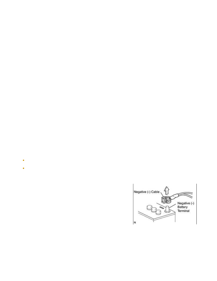
(2) When disconnecting the cable, turn the ignition switch OFF

and headlight dimmer switch OFF and loosen the cable nut

completely. Perform these operations without twisting or

prying the cable. Then disconnect the cable.

(3) Clock settings, radio settings, audio system memory, DTCs

and other data are erased when the cable is disconnected

from the negative (-) battery terminal. Write down any

necessary data before disconnecting the cable.

(4) Certain systems need to be initialized after disconnecting and

reconnecting the cable from the negative (-) battery

terminal.

(b) HANDLING OF ELECTRONIC PARTS

rendered inoperative by static electricity.

(2) Do not pull the wires when disconnecting electronic connectors. Pull the connector.

(3) Be careful not to drop electronic components, such as sensors or relays. If they are dropped on a hard

surface, they should be replaced.

(4) When cleaning the engine with steam, protect the electronic components, air filter and emission-

related components from water.

(5) Never use an impact wrench to remove or install temperature switches or temperature sensors.

4. REMOVAL AND INSTALLATION OF FUEL CONTROL PARTS

(a) PLACE FOR REMOVING AND INSTALLING FUEL SYSTEM PARTS

(1) Work in a location with good air ventilation that does not have welders, grinders, drills, electric motors,

stoves, or any other ignition sources.

(2) Never work in a pit or near a pit as vaporized fuel will collect in those places.

(b) REMOVING AND INSTALLING FUEL SYSTEM PARTS

(1) Prepare a fire extinguisher before starting the operation.

(2) To prevent static electricity, install a ground wire to the fuel changer, vehicle and fuel tank, and do not

spray the surrounding area with water. Be careful when performing work in this area, as the work

surface will become slippery. Do not clean up gasoline spills with water, as this may cause the gasoline

to spread, and possibly create a fire hazard.

(3) Avoid using electric motors, working lights and other electric equipment that can cause sparks or high

temperatures.

(4) Avoid using iron hammers as they may create sparks.

(a) If any metal particles enter inlet system parts, they may

damage the engine.

(c) When installing inlet system parts, check that no metal particles have entered the engine or the installed

parts.

6. HANDLING OF HOSE CLAMPS

(a) Before removing the hose, check the clamp position so that it

can be reinstalled in the same position.

(b) Replace any deformed or dented clamps with new ones.

(c) When reusing a hose, attach the clamp on the clamp track

7. FOR VEHICLES EQUIPPED WITH MOBILE COMMUNICATION SYSTEMS

components.

(c) Keep the antenna and feeder separate from other wiring as much as possible. This will prevent signals

from the communication equipment from affecting vehicle equipment and vice versa.

(d) Check that the antenna and feeder are correctly adjusted.

(e) Do not install a high-powered mobile communication system.

8. HEADLIGHT INSPECTION MAINTENANCE

(a) When the headlights are illuminated, do not cover the headlights

for 3 minutes or more.

NOTICE:

9. FOR VEHICLES EQUIPPED WITH TRAC (TRACTION CONTROL) SYSTEM AND VSC (VEHICLE

STABILITY CONTROL) SYSTEM

(a) NOTICES FOR WHEN TESTING WITH 2-WHEEL DRUM TESTER

HINT:

For 4WD vehicles, make sure that the transfer is in 2WD mode.

(1) When testing with a 2-wheel drum tester such as a speedometer tester, a combination tester for the

speedometer and brake, a chassis dynamometer, enter maintenance mode, or switch to VSC OFF mode

to turn TRAC and VSC operation off. Then enter test mode, start the engine and perform

measurements.

CAUTION:

If the vehicle is tested in normal mode on the drum tester, TRAC and VSC operation may cause the vehicle
to jump out from the drum tester.


Content   ..  8  9  10  11   ..