Suzuki Grand Vitara JB627. Manual - part 275


  Index      Suzuki     Suzuki Grand Vitara JB627 - service repair manual


Search            


Content   ..  273  274  275  276   ..


Suzuki Grand Vitara JB627. Manual - part 275


7B-16 Air Conditioning System: 

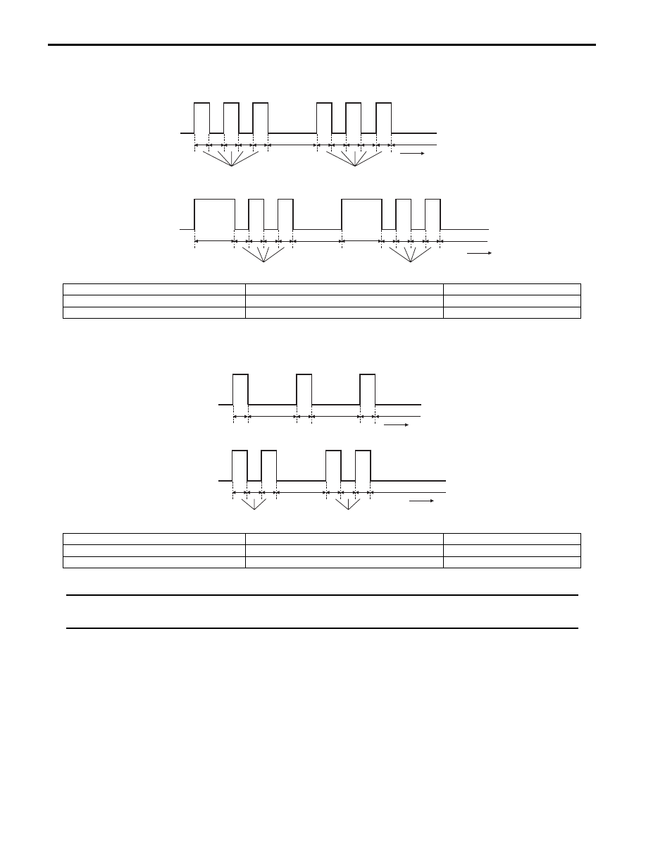
Example of “REC” Indicator Light Flashing Pattern

Example of “FRE” Indicator Light Flashing Pattern

NOTE
Locked actuator, data error and refrigerant pressure malfunction are indicated by flashing pattern of 
“FRE” indicator light specified for each of them.


[A]

(a)

(b)

(d)

(c)

(e)

(d)

[B]

(a)

(b)

(d)

(c)

(e)

(f)

(f)

(d)

I5JB0A720017-01

[A]: B1503 (No.3)

(b): “REC” indicator light “OFF”

(e): 2.0 (sec.)

[B]: B1556 (No.12)

(c): Time (sec.)

(f): 1.5 (sec.)

(a): “REC” indicator light “ON”

(d): 0.5 (sec.)

[A]: Open

(b): “FRE” indicator light “OFF”

(e): 2.0 (sec.)

[B]: Short

(c): Time (sec.)

(a): “FRE” indicator light “ON”

(d): 0.5 (sec.)

[A]

(a)

(b)

[B]

(a)

(b)

(d)

(e)

(e)

(c)

(d)

(e)

(c)

(d)

(d)

I5JB0A720018-01

Air Conditioning System:  7B-17

Display Timing of “FRE” Indicator Light and “REC” Indicator Light
Code with short display time waits until display of code with long display time is over.

Fail-Safe Table

S6JB0B7204005

When any of the following malfunctions (DTCs) is detected, HVAC control module enters fail-safe mode.
However, when HVAC control module detects normal operation of A/C system, fail-safe mode is canceled.

[A]: B1520 (15 – 1)

(a): “REC” indicator flashing pattern

[B]: B1562 (1 – 4)

(b): “FRE” indicator flashing pattern

DTC No.

Trouble Area

Fail-Safe Operation

When ignition switch is turned 

ON after malfunction is already 

detected

When malfunction is detected during 

ignition switch is ON

)

 B1502

Inside air temperature 
sensor and/or its circuit 
malfunction 

HVAC control module controls actuators assuming that inside air 
temperature is 25 

°C (77 °F).

)

 B1503

Evaporator temperature 
sensor and/or its circuit 
malefaction

HVAC control module controls actuators assuming that amount of 
evaporator temperature is –6 

°C (21.2 °F).

)

 B1504

Sunload sensor and/or its 
circuit malfunction 

HVAC control module controls actuators assuming that amount of sunlight 
is 0 W/m

2

.

)

 B1511

Temperature control 
actuator (position sensor) 
and/or its circuit malfunction 

Circuit open: Temperature control actuator fixed to “MAX HOT” position.
Circuit short: Temperature control actuator fixed to “MAX HOT” position.

)

 B1512

Air flow control actuator 
(position sensor) and/or its 
circuit malfunction 

Circuit open: Air flow control actuator fixed to “DEF” position.
Circuit short: Air flow control actuator fixed to “DEF” position.

)

 B1513

Temperature control 
actuator and/or its circuit 
malfunction 

Stop the operation of temperature control actuator.

)

 B1514

Air flow control actuator 
and/or its circuit malfunction 

Stop the operation of Air flow control actuator.

)

 B1520

Temperature selector 
malfunction 

HVAC control module keeps 
condition just before malfunction is 
detected.

HVAC control module controls 
actuators assuming that setting of 
temperature selector is 25 

°C (77 °F).

)

 B1521

Blower speed selector 
malfunction 

HVAC control module keeps 
condition just before malfunction is 
detected.

HVAC control module controls 
actuators assuming that as follows.
• Blower speed is minimum.
• Air flow control actuator fixed to 

“DEF” position.

)

 B1530

Air intake control actuator 
(position sensor) and/or its 
circuit malfunction 

Circuit open: Air intake control actuator fixed to “FRE” position.
Circuit short: Air intake control actuator fixed to “FRE” position.

)

 B1531

Air intake control actuator 
and/or its circuit malfunction 

Stop the operation of temperature control actuator.

[A]

(a)

(b)

[B]

(a)

(b)

I5JB0A720019-02

7B-18 Air Conditioning System: 

Scan Tool Data

S6JB0B7204006

As the data values given below are standard values estimated on the basis of values obtained from the normally 
operating vehicles by using a scan tool, use them as reference values. Even when the vehicles are in good condition, 
there may be cases where the checked values do not fall within each specifies data range. Therefore, judgement as 
abnormal should not be made by checking with these data alone.

)

 B1551 Serial communication circuit 

malfunction

HVAC control module keeps 
condition just before malfunction is 
detected.

HVAC control module controls 
actuators assuming that as follows.
• Outside air temperature is 20 

°C (68 

°F).

• Engine coolant temperature is 90 

°C 

(194 

°F).

• Vehicle speed is 0 km/h (0 mph).
• Engine speed is 0 rpm.

)

 B1552

)

 B1553

CAN communication circuit 
malfunction

)

 B1556

Camshaft position (CMP) 
sensor and/or its circuit 
malfunction

HVAC control module keeps 
condition just before malfunction is 
detected.

HVAC control module controls 
actuators assuming that amount of 
engine speed is 0 rpm.

)

 B1557

Vehicle speed sensor and/
or its circuit malfunction

HVAC control module keeps 
condition just before malfunction is 
detected.

HVAC control module controls 
actuators assuming that amount of 
vehicle speed is 0 km/h (0 mph).

)

 B1561

Engine coolant temperature 
sensor and/or its circuit 
malfunction

HVAC control module keeps 
condition just before malfunction is 
detected.

HVAC control module controls 
actuators assuming that amount of 
engine coolant temperature is 90 

°C 

(194 

°F).

)

 B1562

Outside air temperature 
sensor and/or its circuit 
malfunction

HVAC control module keeps 
condition just before malfunction is 
detected.

HVAC control module controls 
actuators assuming that amount of 
outside air temperature is 20 

°C (68 °F).

DTC No.

Trouble Area

Fail-Safe Operation

When ignition switch is turned 

ON after malfunction is already 

detected

When malfunction is detected during 

ignition switch is ON

Scan Tool Data

Condition

Normal Condition / 

Reference Value

)

 TEMP CONT SWITCH

Each reference value is relative to the position of 
temperature selector of HVAC control module.

Max Cool, 20 

°C (65 °F)

– 30 

°C (85 °F), Max Hot

)

 CABIN TEMPERATURE

Reference value is relative to in car temperature.

–40 

°C – 87.5 °C

(–40 

°F – 189.5 °F) 

)

 OUT SIDE AIR TEMP

Reference value is relative to outside air temperature.

–40 

°C – 87.5 °C

(–40 

°F – 189.5 °F)

)

 EVAPORATOR TEMP

Reference value is relative to temperature of evaporator.

–40 

°C – 87.5 °C

(–40 

°F – 189.5 °F) 

)

 COOLANT TEMP

At specified idle speed after warming up

–40 

°C – 215 °C

(–40 

°F – 419 °F)

)

 SUN LOAD

Reference value depends on the situation.

0 W/m

2

 – 4447.8 W/m

2

)

 MODE CONT SWITCH

Each reference value is relative to the position of airflow 
selector of HVAC control module.

AUTO, VENT, BI-LEVEL, 

FOOT, DEF-FOOT DEF

)

 FAN CONT SWITCH

Each reference value is relative to the position of blower 
speed selector of HVAC control module.

AUTO, OFF 1st, 2nd – 7th, 

8th

)

 FAN DESIRE VOLT

Reference value is relative to the position of blower 
speed selector of HVAC control module.

0 – 16.0 V

)

 AIR MIX POS SENSOR

Reference value is relative to the position of 
temperature selector of HVAC control module.

Approx. 1.5 V (Max Hot)

Approx. 4.5 V (Max Cool)

)

 R/F POS SENSOR

Reference value is relative to the position of air intake 
selector of HVAC control module. (LH steering vehicle)

Approx. 4.0 V (REC)

Approx. 0.9 V (FRE)

)

 R/F POS SENSER

Reference value is relative to the position of air intake 
selector of HVAC control module. (RH steering vehicle)

Approx. 0.9 V (REC)

Approx. 4.0 V (FRE)

)

 MODE POS SENSOR

Reference value is relative to the position of airflow 
selector of HVAC control module.

Approx. 0.5 V (DEF)

Approx. 4.5 V (VENT)

Air Conditioning System:  7B-19

Scan Tool Data Definitions
TEMP CONT SWITCH:  
Position of temperature control 

selector of HVAC control module

CABIN TEMPERATURE:  In-car temperature detected 

by inside air temperature sensor installed in HVAC 
control module

OUTSIDE AIR TEMP (OUTSIDE AIR 

TEMPERATURE):  Outside air temperature 
detected by outside air temperature sensor installed 
in front bumper member

EVAPORATOR TEMP:  Temperature of air passed 

through evaporator

COOLANT TEMP:  Engine coolant temperature 

detected by engine coolant temperature sensor

SUN LOAD:  Amount of sunlight detected by sunload 

sensor installed on the driver side on the dashboard

MODE CONT SWITCH:  Position of airflow selector of 

HVAC control module

FAN CONT SWITCH:  Position of air speed selector of 

HVAC control module

FAN DESIRE VOLT:  Voltage for blower motor
AIR MIX POS SENSOR:  Input signal from position 

sensor in temperature control actuator

MODE POS SENSOR:  Input signal form position 

sensor in air flow control actuator

R/F POS SENSOR (AIR FLOW CONTROL ACTUATOR 

POSITION SENSOR):  Input signal from position 
sensor in air intake control actuator

A/C CONT SIG (ON or OFF):  State of A/C indicator 

light

AIR INTAKE MODE (FRE, REC or MIX):  State of air 

intake mode 

A/C COMP CLUCH:  State of magnet clutch
REFRIGERANT PRESSURE (A/C REFRIGERANT 

ABSOLUTE PRESSURE):  This parameter 
indicates A/C refrigerant absolute pressure 
calculated by ECM

A/C INDICATOR LIGHT (ON or OFF):  State of A/C 

indicator light

FRE INDICATOR LIGHT (ON or OFF):  State of fresh 

air (FRE) indicator light

REC INDICATOR LIGHT (ON or OFF):  State of 

recirculation air (REC) indicator light

REAR DEF INDICATOR (ON or OFF):  State of rear 

defogger indicator light

VEHICLE SPEED:  It is computed based on pulse 

signals from vehicle speed sensor

ENGINE SPEED:  It is computed by signal from CMP 

sensor

)

 A/C CONT SIG

A/C system is ON.

ON

A/C system is OFF.

OFF

)

 AIR INTAKE MODE

Fresh air (FRE) mode is activated.

FRE

Recirculation air (REC) mode is activated.

REC

AUTO mode is activated.

AUTO

)

 A/C COMP CLUCH

Magnet clutch is engaged.

ON

Magnet clutch is not engaged.

OFF

)

 REFRIGERANT PRESSURE

Engine 
running.

A/C ON (A/C is operating) at ambient 
temperature: 30 

°C (86 °F)

1350 – 1650 kPa for more 

details, refer to pressure of 

high pressure gauge under 

“A/C System Performance 

Inspection”.

A/C ON (A/C is not operating) at ambient 
temperature: 30 

°C (86 °F) and engine coolant 

temperature: 90 

°C – 100 °C (194 °F – 212 °F)

600 – 1000 kPa after 

longer than 10 min from A/

C switch turned off.

)

 A/C INDICATOR LIGHT

A/C indicator light is lighted.

ON

A/C indicator light is not lighted.

OFF

)

 FRE INDICATOR LIGHT

Fresh air (FRE) indicator light is lighted.

ON

Fresh air (FRE) indicator light is not lighted.

OFF

)

 REC INDICATOR LIGHT

Recirculation air (REC) indicator light is lighted.

ON

Recirculation air (REC) indicator light is not lighted.

OFF

)

 REAR DEF INDICATOR

Rear defogger indicator light is lighted.

ON

Rear defogger indicator light is not lighted.

OFF

)

 VEHICLE SPEED

At stop.

0 km/h (0 mph)

)

 ENGINE SPEED

At engine idle speed

Engine idle speed is 

display

Scan Tool Data

Condition

Normal Condition / 

Reference Value


Content   ..  273  274  275  276   ..