Suzuki Grand Vitara JB627. Manual - part 188


  Index      Suzuki     Suzuki Grand Vitara JB627 - service repair manual


Search            


Content   ..  186  187  188  189   ..


Suzuki Grand Vitara JB627. Manual - part 188


4E-33 ABS: 

Repair Instructions

Hydraulic Unit Operation Check

S6JB0B4506001

1) Check that basic brake system other than ABS is in 

good condition.

2) Check that battery voltage is 11 V or higher.
3) Lift up vehicle.
4) Set transmission to neutral and release parking 

brake.

5) Turn each wheel gradually by hand to check if brake 

dragging occurs. If it does, correct.

6) Connect SUZUKI scan tool to data link connector 

(DLC) (1) with ignition switch OFF.

Special tool
(A):  SUZUKI scan tool

7) Turn ignition switch to ON position and select menu 

to “HYDRAULIC CONTROL TEST” under 
“miscellaneous test” (“MISC. TEST”) mode of 
SUZUKI scan tool.

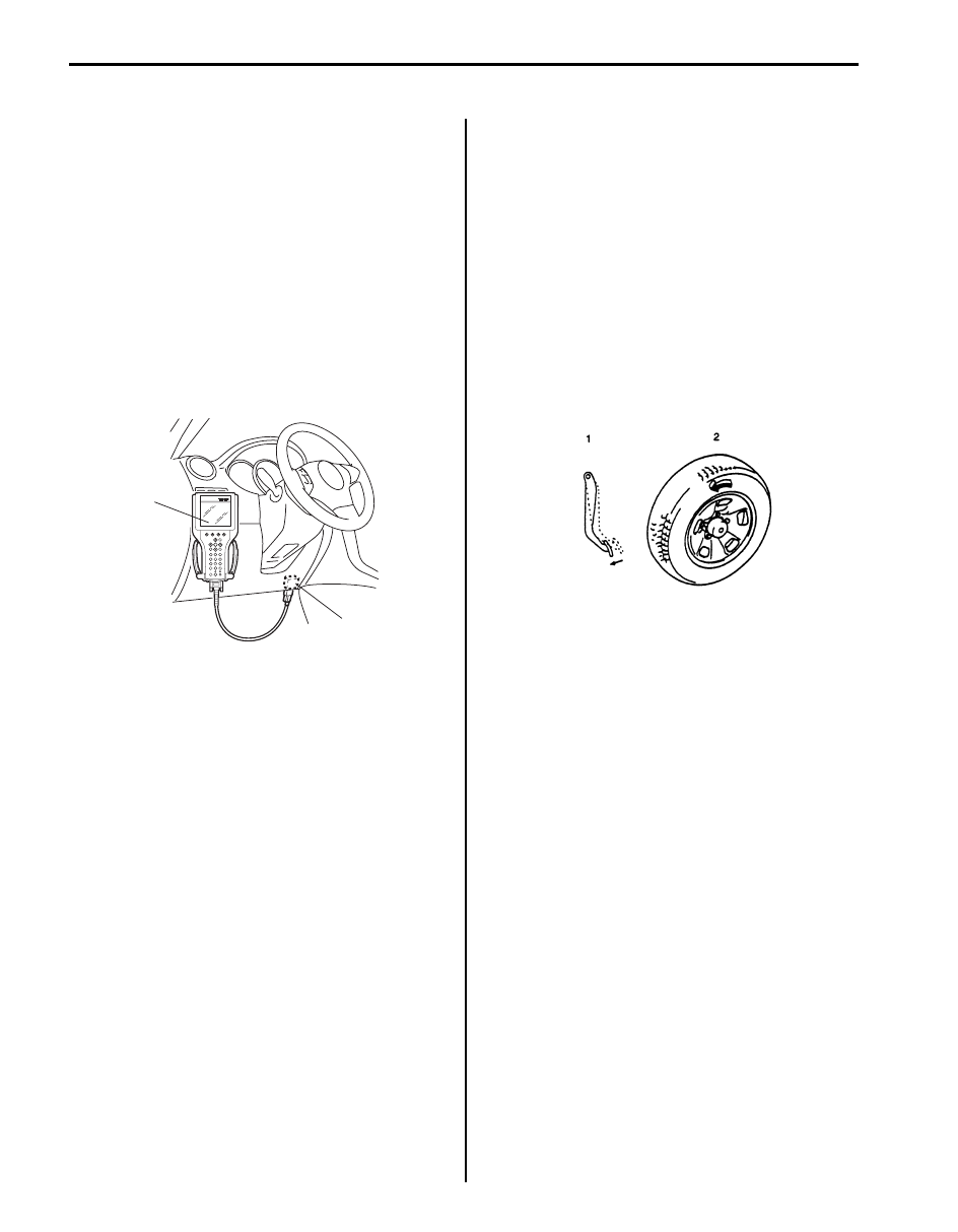
8) Perform the following checks with help of another 

person.
Brake pedal (1) should be depressed and then select 
testing wheel by SUZUKI scan tool and the wheel (2) 
should be turned by another person’s hand. At this 
time, check that:
• Operation sound of solenoid is heard and the 

wheel turns only about 0.5 sec. (Brake force is 
depressurized).

• Operation sound of pump motor is heard and 

pulsation is felt at brake pedal.

9) Check for all 4-wheels condition respectively. If a 

faulty condition is found, replace hydraulic unit / 
control module assembly.

10) After completing the check, turn ignition switch to 

OFF position and disconnect SUZUKI scan tool from 
DLC.

(A)

1

I5JB0A450008-01

I4RH01450021-01

ABS: 4E-34

ABS (ESP

®) hydraulic unit / control module Assembly Components

S6JB0B4506002

CAUTION

!


Never disassemble ABS (ESP

®) hydraulic unit / control module assembly, loosen blind plug or remove 

motor. Performing any of these prohibited services will affect original performance of ABS (ESP

®

hydraulic unit / control module assembly.


5

2

(c)

(d)

3

(a)

(c)

(d)

(a)

4

1

(b)

(a)

[A]

[B]

I6JB01450015-05

[A]: ESP

® model

3. Bracket

:  19 N

⋅m (1.9 kgf-m, 14.0 lb-ft)

[B]: Non-ESP

® model

4. ESP

® control module connector

:  9 N

⋅m (0.9 kgf-m, 6.5 lb-ft)

1. ESP

® hydraulic unit / control module assembly

5. ABS control module connector

: 25 N

⋅m (2.5 kgf-m, 18.0 lb-ft)

2. ABS hydraulic unit / control module assembly

: 16 N

⋅m (1.6 kgf-m, 11.5 lb-ft)

4E-35 ABS: 

ABS (ESP

®) hydraulic unit / control module 

Assembly On-Vehicle Inspection

S6JB0B4506003

CAUTION

!


Never disassemble ABS (ESP

®) hydraulic 

unit / control module assembly, loosen blind 
plug or remove motor. Performing any of 
these prohibited services will affect original 
performance of ABS (ESP

®) hydraulic unit / 

control module assembly.


Check hydraulic unit for fluid leakage.
If any, repair or replace.

ABS (ESP

®) hydraulic unit / control module 

Assembly Removal and Installation

S6JB0B4506004

CAUTION

!


Never disassemble ABS (ESP

®) hydraulic 

unit / control module assembly, loosen blind 
plug or remove motor. Performing any of 
these prohibited services will affect original 
performance of ABS (ESP

®) hydraulic unit / 

control module assembly.


NOTE

• For ESP

® model, be sure to perform 

“Sensor Calibration in Section 4F” before 
performing hydraulic unit operation check 
when ESP

® hydraulic unit / control module 

is replaced.

• When ignition switch is turned to ON 

position after replacing ESP

® hydraulic 

unit / control module, DTC C1075, C1076, 
C1078 and C1077 are stored in ESP

® 

control module and the following lights 
light up or flash. However, these are in 
normal operation. These DTCs are cleared 
and lights are turned off if the following 
operations are performed in order.
1) “Sensor Calibration in Section 4F”.
2) “Hydraulic Unit Operation Check”.
3) Ignition switch OFF and ON.


1. ABS warning light

4. SLIP indicator light

2. EBD warning light (brake warning light)

5. ESP

® OFF light

3. ESP

® warning light

3

2

1

4

5

I6JB01460002-02

ABS: 4E-36

Removal

1) Disconnect negative cable from battery.
2) Remove ECM referring to “Engine Control Module 

(ECM) Removal and Installation in Section 1C”.

3) Disconnect ABS (ESP

®) hydraulic unit / control 

module assembly connector (1) as shown in figure.

4) Using special tool, loosen flare nuts (1) and 

disconnect brake pipes (2) from ABS (ESP

®) 

hydraulic unit / control module assembly (3).

Special tool
(A):  09950–78220

NOTE
Put bleeder plug cap or the like onto pipe to 
prevent fluid from spilling. Do not allow brake 
fluid to get on painted surfaces.


5) Disconnect harness clamps (4) from bracket (5).

6) Remove ABS (ESP

®) hydraulic unit / control module 

with bracket from vehicle by removing bracket bolt 
and two bracket nuts.

7) Remove bolt and pull out ABS (ESP

®) hydraulic unit 

/ control module assembly (1) from bracket (3) using 
flat end rod or the like (2).

CAUTION

!


• Do not give an impact to hydraulic unit.
• Use care not to allow dust to enter 

hydraulic unit.

• Do not place hydraulic unit on its side or 

upside down. Handling it in inappropriate 
way will affect its original performance.


[A]: ESP

® model

1. ESP

® control module connector 

[B]: Non-ESP

® model

2. ABS control module connector

C: Pull up to disconnect

3. Lock

D: Pull down to disconnect

3

1

[A]

[B]

C

D

3

2

I6JB01450016-02

3

2

4

5

1

(A)

I5JB0A450023-01

2

1

3

I5JB0A450024-01


Content   ..  186  187  188  189   ..