Suzuki Grand Vitara JB627. Manual - part 93


  Index      Suzuki     Suzuki Grand Vitara JB627 - service repair manual


Search            


Content   ..  91  92  93  94   ..


Suzuki Grand Vitara JB627. Manual - part 93


1D-53 Engine Mechanical: 

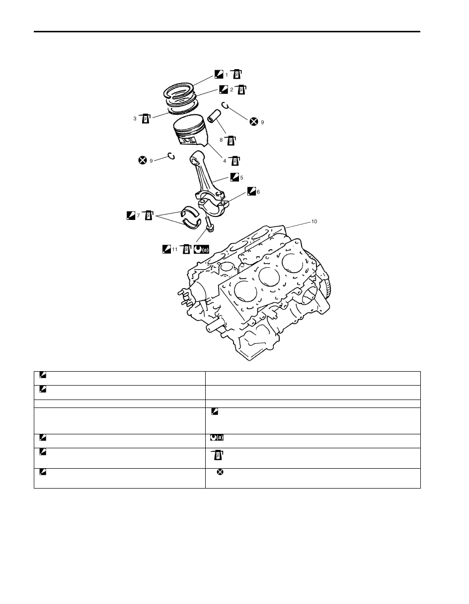
Pistons, Piston Rings, Connecting Rods and Cylinders Components

S6JB0B1406037

I6JB01140090-01

1. Top ring

: “RN” mark provided on piston ring comes to facing up.

8. Piston pin

2. 2nd ring

: “R” mark provided on piston ring comes to facing up.

9. Piston pin circlip

3. Oil ring

10. Cylinder block

4. Piston

11. Connecting rod bolt

: Check connecting rod bolt referring to “Connecting Rod Bolt Deformation 
(Plastic Deformation Tightening Bolt)” under “Crank Pins and Connecting Rod 
Bearings Inspection” if it
 is reused.

5. Connecting rod

: Do not apply engine oil to inner surface of big end.

: Tighten 15 N

⋅m (1.5 kgf-m, 11.0 lb-ft), 45° and 45° by the specified procedure.

6. Connecting rod bearing cap

: Point arrow mark on cap to crankshaft pulley side. Do not 
apply engine oil to inner surface of bearing cap.

: Apply engine oil to sliding surface of each part.

7. Connecting rod bearing

: Do not apply engine oil between connecting rod big end and 
bearing, between cap and bearing.

: Do not reuse.

Engine Mechanical:  1D-54

Pistons, Piston Rings, Connecting Rods and 
Cylinders Removal and Installation

S6JB0B1406038

Removal

1) Remove engine assembly from vehicle referring to 

“Engine Assembly Removal and Installation”.

2) Remove cylinder heads. Refer to “Valves and 

Cylinder Heads Removal and Installation”.

3) Remove oil pump. Refer to “Oil Pump and Oil Pump 

Chain Removal and Installation in Section 1E”.

4) Mark cylinder number on all pistons, connecting rods 

and connecting rod bearing caps.

5) Remove connecting rod bearing caps.
6) Clean carbon from top of cylinder bore before 

removing piston from cylinder.

7) Push piston and connecting rod assembly out 

through the top of cylinder bore.

Installation

1) Apply engine oil to pistons, rings, cylinder walls, 

connecting rod bearings and crank pins.

NOTE
Do not apply oil between connecting rod and 
bearing or between bearing cap and bearing.


2) When installing piston and connecting rod assembly 

into cylinder bore, point mark (1) on piston head to 
crankshaft pulley side (2).

3) Install piston and connecting rod assembly into 

cylinder bore. Use special tool (Piston ring 
compressor) to compress rings. Guide connecting 
rod into place on crankshaft.
Using a hammer handle, tap piston head to install 
piston into bore. Hold ring compressor firmly against 
cylinder block until all piston rings have entered 
cylinder bore.

Special tool
(A):  09916–77310

4) Install connecting rod bearing cap (1) as follows.

NOTE
If connecting rod bolt is reused, mark sure to 
check connecting rod bolt for deformation 
referring to “Connecting Rod Bolt 
Deformation (Plastic Deformation Tightening 
Bolt)” under “Crank Pins and Connecting 
Rod Bearings Inspection”.


a) Point arrow mark (2) on cap to crankshaft pulley 

side.

b) Apply engine oil to new connecting rod bolts (3).
c) Tighten all connecting rod bolts to 15 N

⋅m (1.5 

kgf-m, 11.0 lb-ft).

d) Retighten them by turning through 45

°

e) Repeat step d) once again.

Tightening torque
Connecting rod bolt (a):  Tighten 15 N

m (1.5 

kgf-m,11.0 lb-ft), 45

° and 45° by the specified 

procedure.

IYSQ01143128-01

IYSQ01141111-01

I6JB01140091-01

1D-55 Engine Mechanical: 

5) Install cylinder heads to cylinder block referring to 

“Valves and Cylinder Heads Removal and 
Installation”.

6) Install oil pump to cylinder block referring to “Oil 

Pump and Oil Pump Chain Removal and Installation 
in Section 1E”.

7) Install tappets, shims and camshafts referring to 

“Camshafts, Tappets and Shims Removal and 
Installation”.

8) Install RH (No.2) bank 2nd timing chain referring to 

“RH (No.2) Bank 2nd Timing Chain and Chain 
Tensioner Removal and Installation”.

9) Install 1st timing chain. Refer to “1st Timing Chain 

and Chain Tensioner Removal and Installation”.

10) Install LH (No.1) bank 2nd timing chain. Refer to “LH 

(No.1) Bank 2nd Timing Chain and Chain Tensioner 
Removal and Installation”.

11) Install timing chain cover. Refer to “Timing Chain 

Cover Removal and Installation”.

12) Install oil pans and pump strainer. Refer to “Oil Pan 

and Oil Pump Strainer Removal and Installation in 
Section 1E”
.

13) Install cylinder head covers. Refer to “Cylinder Head 

Covers Removal and Installation”.

14) Install exhaust manifold. Refer to “Exhaust Manifold 

Removal and Installation in Section 1K”.

15) Install radiator outlet pipe.

Refer to “Cooling Water Pipes or Hoses Removal 
and Installation in Section 1F”.

16) Install intake manifold, intake collector and electric 

throttle body assembly referring to “Intake Collector 
and Intake Manifold Removal and Installation” an

“Electric Throttle Body Assembly Removal and 
Installation”.

17) Install engine assembly to vehicle referring to 

“Engine Assembly Removal and Installation”.

Pistons, Piston Rings, Connecting Rods and 
Cylinders Disassembly and Reassembly

S6JB0B1406039

Disassembly

1) Using piston ring expander, remove two 

compression rings (Top and 2nd) and oil ring from 
piston.

2) Remove piston pin from connecting rod.

a) Ease out piston pin circlips (1) as shown in 

figure.

b) Force piston pin out.

IYSQ01141113-01

IYSQ01141114-01

Engine Mechanical:  1D-56

Reassembly

1) 2 sizes of piston are available as standard size spare part so as to ensure proper piston-to-cylinder clearance. 

When installing a standard size piston, make sure to match piston with cylinder as follows.
a) Each piston (8) has stamped number (9) on its piston head. It represents outer diameter of piston.
b) There are also stamped numbers (10) or painted color (10) on cylinder block as shown in figure. 
c) Stamped number on piston and painted color (stamped number) on cylinder block must correspond. That is, 

install number “2” stamped piston to cylinder which is identified with blue painted (or “2” stamped) and a 
number “1” piston to cylinder with red painted (or “1” stamped).

Piston outer diameter and cylinder bore diameter

Piston-to-cylinder clearance
0.02 – 0.04 mm (0.0008 – 0.0015 in.)

Piston

Cylinder

Number

Outer diameter

Number 

(Paint)

Bore diameter

1

87.9800 – 87.9900 mm

(3.4638 – 3.4641 in.)

1 (Red)

88.0101 – 88.0200 mm

(3.4650 – 3.4653 in.)

2

87.9700 – 87.9799 mm

(3.4633 – 3.4637 in.)

2 (Blue)

88.0000 – 88.0100 mm

(3.4646 – 3.4649 in.)

1. No.1 cylinder

4. No.4 cylinder

7. Crankshaft pulley side

2. No.2 cylinder

5. No.5 cylinder

3. No.3 cylinder

6. No.6 cylinder

I6JB01140092-01


Content   ..  91  92  93  94   ..