Suzuki Grand Vitara JB627. Manual - part 94


  Index      Suzuki     Suzuki Grand Vitara JB627 - service repair manual


Search            


Content   ..  92  93  94  95   ..


Suzuki Grand Vitara JB627. Manual - part 94


1D-57 Engine Mechanical: 

2) Install piston pin to piston and connecting rod:

After applying engine oil to piston pin and piston pin 
holes in piston (1) and connecting rod (3), fit 
connecting rod to piston as shown in figure and 
insert piston pin to piston and connecting rod, and 
install piston pin circlips.

NOTE
“59J0” mark on connecting rod must face 
toward crankshaft pulley side.


NOTE

• Install circlip (6) with its cut part facing as 

shown in figure.

• Install so that circlip end gap comes within 

such range as indicated by arrow.


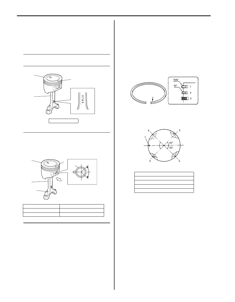
3) Install piston rings to piston:

• As shown in figure, 1st (1) and 2nd rings (2) have 

“RN” or “R” mark respectively. When installing 
these piston rings to piston, direct marked side of 
each ring toward top of piston.

• 1st rings differs from 2nd ring in thickness, shape 

of surface contacting cylinder wall.
Distinguish 1st ring from 2nd ring by referring to 
figure.

• When installing oil ring (3), install spacer first and 

then 2 rails.

4) After installing three rings (1st, 2nd and oil rings), 

distribute their end gaps as shown in figure.

2. Arrow mark

1. Piston

4. Oil hole

2. Arrow mark

5. Crankshaft pulley side

3. Connecting rod

1

2

3

I6JB01140093-01

1

2

3

6

4

5

I6JB01140094-02

1. Mark
2. 1st ring end gap
3. 2nd ring end gap and oil ring spacer gap
4. Oil ring upper rail gap
5. Oil ring lower rail gap

I6JB01140095-01

I6JB01140096-01

Engine Mechanical:  1D-58

Cylinders, Pistons and Piston Rings Inspection

S6JB0B1406040

NOTE
Before the following inspection, clean carbon 
from piston head and ring grooves, using a 
suitable tool.


Cylinders
• Inspect cylinder walls for scratches, roughness, or 

ridges which indicate excessive wear. If cylinder bore 
is very rough or deeply scratched, or ridged, rebore 
cylinder and use over size piston.

• Using a cylinder gauge, measure cylinder bore in 

thrust and axial directions at 2 positions (1, 2) as 
shown in figure. If any of the following condition is 
noted, rebore cylinder.
– Cylinder bore via. exceeds limit.
– Difference of measurements at 2 positions exceeds 

taper limit.

– Difference between thrust and axial measurements 

exceeds out-of-round limit.

Cylinder bore
Standard: 88.000 – 88.020 mm (3.4646 – 3.4653 
in.)
Limit: 88.050 mm (3.4665 in.)

Taper and out-of-round
Limit: 0.10 mm (0.004 in.)

NOTE
If any one of six cylinders has to be rebored, 
rebore all six to the same oversize. This is 
necessary for the sake of uniformity and 
balance.


Pistons
• Inspect piston for faults, cracks or other damages.

Damaged or faulty piston should be replaced.

• Piston diameter:

As shown in figure, piston diameter should be 
measured at a position 26.5 mm (1.04 in.) (“a”) from 
piston skirt end in the direction perpendicular to piston 
pin.

Piston diameter
Standard: 87.970 – 87.990 mm (3.4634 – 3.4641 in.)
Oversize (0.50 mm): 88.470 – 88.490 mm (3.4831 – 
3.4838 in.)

• Piston clearance:

Measure cylinder bore diameter and piston diameter 
to find their difference which is piston clearance. 
Piston clearance should be within specification as 
given below. If it is out of specification, rebore cylinder 
and use oversize piston.

Piston-to-cylinder clearance
0.02 – 0.04 mm (0.0008 – 0.0015 in.)

NOTE
Cylinder bore diameter should be measured 
in 2 places 90 degrees apart.


1. 50 mm (1.96 in.)

2. 95 mm (3.74 in.)

I5JA01140018-01

“a”: 26.5 mm (1.04 in.)

“a”: 26.5 mm (1.04 in.)

IYSQ01141121-01

I5JA01140019-01

1D-59 Engine Mechanical: 

• Ring groove clearance:

Before checking, piston grooves must be clean, dry 
and free of carbon.
Fit new piston ring (1) into piston groove, and 
measure clearance between ring and ring land by 
using thickness gauge (2). If clearance is out of 
specification, replace piston.

Ring groove clearance
Top: 0.03 – 0.07 mm (0.0012 – 0.0027 in.)
2nd: 0.02 – 0.06 mm (0.0008 – 0.0023 in.)

Piston Rings
To measure end gap, insert piston ring into cylinder bore 
and then measure the gap by using thickness gauge.
If measure gap is out of specification, replace ring.

NOTE
Clean carbon and any other dirt from top of 
cylinder bore before inserting piston ring.


Piston ring end gap 

Piston Pins and Connecting Rods Inspection

S6JB0B1406041

Piston Pins
• Check piston pin, connecting rod small end bore and 

piston bore for wear or damage, paying particular 
attention to condition of small end bore bush. If pin, 
connecting rod small end bore or piston bore is badly 
worn or damaged, replace pin, connecting rod or 
piston.

• Piston pin clearance:

Check piston pin clearance in small end. Replace 
connecting rod if its small end is badly worn or 
damaged or if measured clearance exceeds limit.

Piston pin clearance in small end
0.003 – 0.014 mm (0.0001 – 0.0005 in.)

Small-end bore
21.003 – 21.011 mm (0.8269 – 0.8272 in.)

Piston pin diameter
20.997 – 21.000 mm (0.82665 – 0.82677 in.)

Connecting Rods
• Big-end side clearance:

Check big-end of connecting rod for side clearance, 
with rod fitted and connected to its crank pin in the 
normal manner. If measured clearance is found to 
exceed its limit, replace connecting rod.

Big-end side clearance
Standard: 0.25 – 0.35 mm (0.0099 – 0.0137 in.)
Limit: 0.45 mm (0.0177 in.)

Item

Standard

Limit

Top ring

0.20 – 0.35 mm 

(0.0079 – 0.0137 in.)

0.7 mm 

(0.0276 in.)

2nd ring

0.35 – 0.47 mm 

(0.0138 – 0.0185 in.)

0.7 mm 

(0.0276 in.)

Oil ring

0.20 – 0.70 mm 

(0.0079 – 0.0275 in.)

1.8 mm 

(0.0709 in.)

1. Cylinder block

3. Piston ring

2. Feeler gauge

4. 120 mm (4.72 in.)

I2RH01140159-01

IYSQ01141124-01

I5JA01140020-01

I6JB01140097-01

Engine Mechanical:  1D-60

• Connecting rod alignment:

Mount connecting rod on aligner to check it for bow 
and twist. If limit is exceeded, replace it.

Connecting rod alignment
Limit on bow: 0.05 mm (0.0020 in.)
Limit on twist: 0.10 mm (0.0039 in.)

Crank Pins and Connecting Rod Bearings 
Inspection

S6JB0B1406042

• Inspect crank pin for uneven wear or damage. 

Measure crank pin for out-of-round or taper with a 
micrometer. If crank pin is damaged, or out-of-round 
or taper is out of limit, replace crankshaft or regrind 
crank pin then inspect rod bearing clearance referring 
to “Connecting rod bearing clearance”.

Crank pin diameter

Crank pin out-of-round (a – b)
Limit: 0.01 mm (0.0004 in.)

Crank pin taper (c – d)
Limit: 0.01 mm (0.0004 in.)

• Connecting rod bearing general information:

Service connecting rod bearings are available in 
standard size and 0.25 mm (0.0098 in.) undersize, 
and standard size bearing has 5 kinds of bearings 
differing in tolerance. For identification of undersize 
bearing, it is painted red at the position as indicated in 
figure, undersize bearing thickness is 1.605 – 1.615 
mm (0.0632 – 0.0635 in.) at the center of it.

• Connecting rod bearing visual inspection:

Inspect bearing shells for signs of fusion, pitting, burn 
or flaking and observe contact pattern. Bearing shells 
found in defective condition must be replaced.

• Connecting rod bearing clearance:

a. Before checking bearing clearance, clean bearing 

and crank pin.

b. Install bearing in connecting rod and bearing cap.
c. Place a piece of gaging plastic (1) to full width of 

crank pin as contacted by bearing (parallel to 
crankshaft), avoiding oil hole.

d. Install rod bearing cap to connecting rod referring 

to “Pistons, Piston Rings, Connecting Rods and 
Cylinders Removal and Installation”.

NOTE
Do not turn crankshaft with gaging plastic 
installed.


Connecting rod 

bearing size

Crank pin diameter

Standard

49.982 – 50.000 mm
(1.9678 – 1.9685 in.)

0.25 mm (0.0098 in.) 

undersize

49.732 – 49.750 mm
(1.9580 – 1.9586 in.)

IYSQ01143136-01

1. Painting

IYSQ01141169-01

I6JB01140098-01


Content   ..  92  93  94  95   ..