Suzuki Grand Vitara JB627. Manual - part 91


  Index      Suzuki     Suzuki Grand Vitara JB627 - service repair manual


Search            


Content   ..  89  90  91  92   ..


Suzuki Grand Vitara JB627. Manual - part 91


1D-45 Engine Mechanical: 

Valves and Cylinder Heads Removal and 
Installation

S6JB0B1406032

Removal

1) Remove engine assembly from vehicle referring to 

“Engine Assembly Removal and Installation”.

2) Remove camshafts, tappets and shims referring to 

“Camshafts, Tappets and Shims Removal and 
Installation”.

3) Remove exhaust manifold referring to “Exhaust 

Manifold Removal and Installation in Section 1K”.

4) Remove water outlet cap.
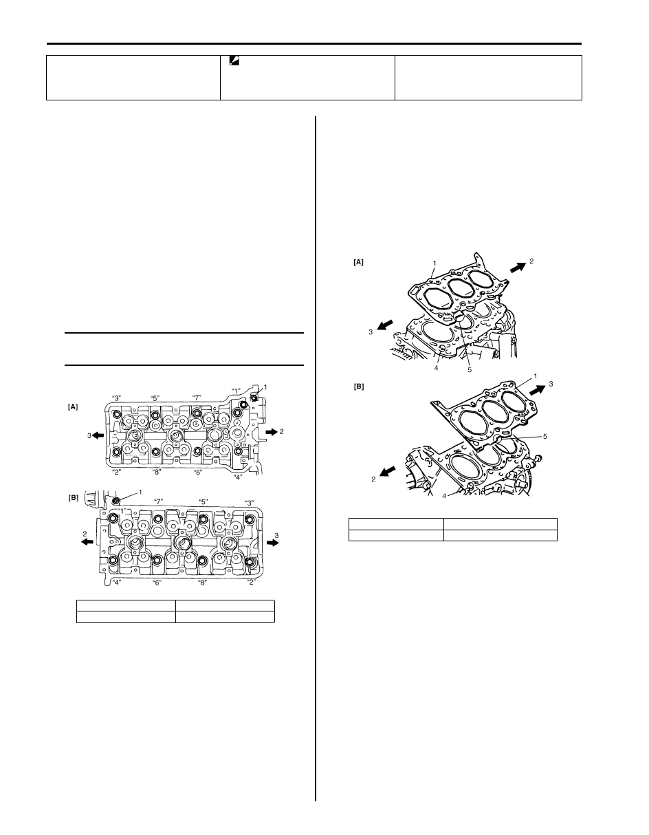
5) Loosen cylinder head bolts in such order (“1” 

→ “8”) 

as shown in figure and remove them.

NOTE
Be sure to remove 2 hex bolts (1) shown in 
figure.


6) Remove cylinder heads.

Installation

1) Clean mating surface on cylinder head and cylinder 

block. Remove oil, old gasket and dust from mating 
surface.

2) Install knock pin (4) to cylinder block.
3) Install new cylinder head gasket (1) to cylinder block 

as shown in figure. Carved lot number (5) on cylinder 
head gasket (1) should face up (toward cylinder 
head side).

7. Intake valve

14. Cylinder head bolt

: Check cylinder head bolt (M10) for 
deformation referring to “Cylinder Head 
Bolt” under “Valves and Valve Guides 
Inspection”,
 if it is reused.

[A]: RH (No.2) bank

2. Timing chain side

[B]: LH (No.1) bank

3. Flywheel side

I6JB01140086-01

[A]: RH (No.2) bank

2. Crankshaft pulley side

[B]: LH (No.1) bank

3. Flywheel side

I6JB01140087-01

Engine Mechanical:  1D-46

4) Install cylinder head to block.

After applying oil to cylinder head bolts, tighten them 
gradually as follows.
a) Tighten cylinder head bolts (except hex hole bolt) 

to 53 N

⋅m (5.3 kgf-m, 38.5 lb-ft) according to 

numerical order in figure.

b) In the same manner as Step a), tighten them to 

84 N

⋅m (8.4 kgf-m, 61.0 lb-ft).

c) Loosen all bolts until tightening torque is reduced 

to 0 in reverse order of tightening.

d) In the same manner as Step a), tighten them to 

53 N

⋅m (5.3 kgf-m, 38.5 lb-ft).

e) In the same manner as Step a) again, tighten 

them to 105 N

⋅m (10.5 kgf-m, 76.0 lb-ft).

f) Tighten cylinder head bolts (hex hole bolt) to 

specified torque.

Tightening torque
Cylinder head bolt (a):  Tighten 53 N

m (5.3 

kgf-m, 38.5 lb-ft), 84 N

m (8.4 kgf-m, 61.0 lb-ft), 

0 N

m (0 kgf-m, 0 lb-ft), 53 Nm (5.3 kgf-m, 38.5 

lb-ft) and 105 N

m (10.5 kgf-m, 76.0 lb-ft) by 

the specified procedure
Cylinder head bolt (hex hole bolt) (b):  
Tighten 11 N

m (1.1 kgf-m, 7.5 lb-ft) by the 

specified procedure

NOTE
Be sure to install hex hole bolts (1) as shown 
in figure.


5) Install water outlet cap.
6) Check timing mark on crankshaft as shown in figure.

7) Install tappets, shims, camshafts, and RH (No.2) 

bank 2nd timing chain.
Refer to “Camshafts, Tappets and Shims Removal 
and Installation” an
d “RH (No.2) Bank 2nd Timing 
Chain and Chain Tensioner Removal and 
Installation”.

8) Install 1st timing chain referring to “1st Timing Chain 

and Chain Tensioner Removal and Installation”.

9) Install LH (No.1) bank 2nd timing chain referring to 

“LH (No.1) Bank 2nd Timing Chain and Chain 
Tensioner Removal and Installation”.

10) Install timing chain cover referring to “Timing Chain 

Cover Removal and Installation”.

11) Install oil pans and oil pump strainer referring to “Oil 

Pan and Oil Pump Strainer Removal and Installation 
in Section 1E”.

12) Install cylinder head covers referring to “Cylinder 

Head Covers Removal and Installation”.

13) Install exhaust manifold referring to “Exhaust 

Manifold Removal and Installation in Section 1K”.

14) Install radiator outlet pipe referring to “Cooling Water 

Pipes or Hoses Removal and Installation in Section 
1F”.

15) Install intake manifold, intake collector and electric 

throttle body assembly referring to “Intake Collector 
and Intake Manifold Removal and Installation” an

“Electric Throttle Body Assembly Removal and 
Installation”.

16) Install engine assembly to vehicle referring to 

“Engine Assembly Removal and Installation”.

2. Crankshaft pulley side

3. Flywheel side

I6JB01140088-01

1. Crank timing pulley key

2. Oil jet

2

1

I6JB01140089-01

1D-47 Engine Mechanical: 

Valves and Cylinder Heads Disassembly and 
Reassembly

S6JB0B1406033

Disassembly

1) Using special tools (A), (B) and (C), compress valve 

springs and then remove valve cotters (1) by using 
special tool (D).

2) Release special tool, and remove spring retainer and 

valve spring.

Special tool
(A):  09916–14510
(B):  09916–14910
(C):  09919–28610
(D):  09916–84511

3) Remove valve from combustion chamber side.
4) Remove valve stem seal (1) from valve guide, and 

then valve spring seat (2).

NOTE
Do not reuse seal once disassembled. Be 
sure to use new seal when assembling.


5) Using special tool (E) (Valve guide remover), drive 

valve guide out from combustion chamber side to 
valve spring side.

Special tool
(E):  09916–44910

NOTE
Do not reuse valve guide once disassembled. 
Be sure to use new valve guide (Oversize) 
when assembling.


6) Place disassembled parts except valve stem seal 

and valve guide in order so that they can be installed 
in their original positions.

I5JA01140014-01

IYSQ01143116-01

IYSQ01143117-01

Engine Mechanical:  1D-48

Reassembly

1) Before installing valve guide into cylinder head, ream 

guide hole with special tool (11 mm reamer) so as to 
remove burrs and make it truly round.

Special tool
(E):  09916–34542
(F):  09916–38210

2) Install valve guide to cylinder head.

Heat cylinder head uniformly at a temperature of 80 
to 100 

°C (176 to 212 °F) so that head will not be 

distorted, and drive new valve guide into hole with 
special tools. Drive in new valve guide until special 
tool (Valve guide installer) contacts cylinder head.
After installing, make sure that valve guide 
protrusions (1) by specified height from cylinder 
head.

Special tool
(G):  09916–58210
(H):  09917–87810

NOTE

• Do not reuse valve guide once 

disassembled. Install new valve guide 
(Oversize).

• Intake and exhaust valve guides are 

identical.


Outer diameter of oversized valve guide
11.088 – 11.103 mm (0.4365 – 0.4371 in.)

Valve guide protrusion (In and Ex)
13.5 mm (0.53 in.)

3) Ream valve guide bore with special tool (6.0 mm 

reamer). After reaming, clean bore.

Special tool
(E):  09916–34542
(I):  09916–37810

4) Install valve spring seat to cylinder head.
5) Install new valve stem seal (1) to valve guide.

After applying engine oil to seal and spindle of 
special tool (Valve guide installer handle), fit oil seal 
to spindle, and then install seal to valve guide by 
pushing special tool by hand.
After installing, check to be sure that seal is properly 
fixed to valve guide.

Special tool
(J):  09917–98221
(K):  09916–58210

NOTE

• Do not reuse seal once disassembled. Be 

sure to install new seal.

• When installing, never tap or hit special 

tool with a hammer or else. Install seal to 
guide only by pushing special tool by 
hand. Tapping or hitting special tool may 
cause damage to seal.


I5JA01140015-01

IYSQ01143119-01

IYSQ01143120-01


Content   ..  89  90  91  92   ..