Subaru Forester (2019). Manual - part 19
(152,1)
“OPEN” side or “CLOSE” side.
After washing the vehicle or after it rains,
wipe away water on the roof prior to
opening the moonroof to prevent drops of
water from falling into the passenger
compartment.
NOTE
.
Driving with the moonroof fully open
can cause an annoying sound to be
generated at high speeds. If this oc-
curs, use the moonroof at the initial
stop position of 6 in (15 cm) away from
the fully opened position.
.
The moonroof cannot be operated
while the remote engine starter system
is operating.
&
Anti-entrapment function
When the moonroof senses a substantial
enough object trapped between its glass
and the vehicle’s roof during closure, it
automatically moves back to the fully open
position and stops there. The anti-entrap-
ment function may also be activated by a
strong shock on the moonroof even when
there is nothing trapped.
CAUTION
Never attempt to test this function
using fingers, hands or other parts
of your body.
NOTE
For the sake of safety, it is recom-
mended that you avoid driving with the
moonroof fully opened.
&
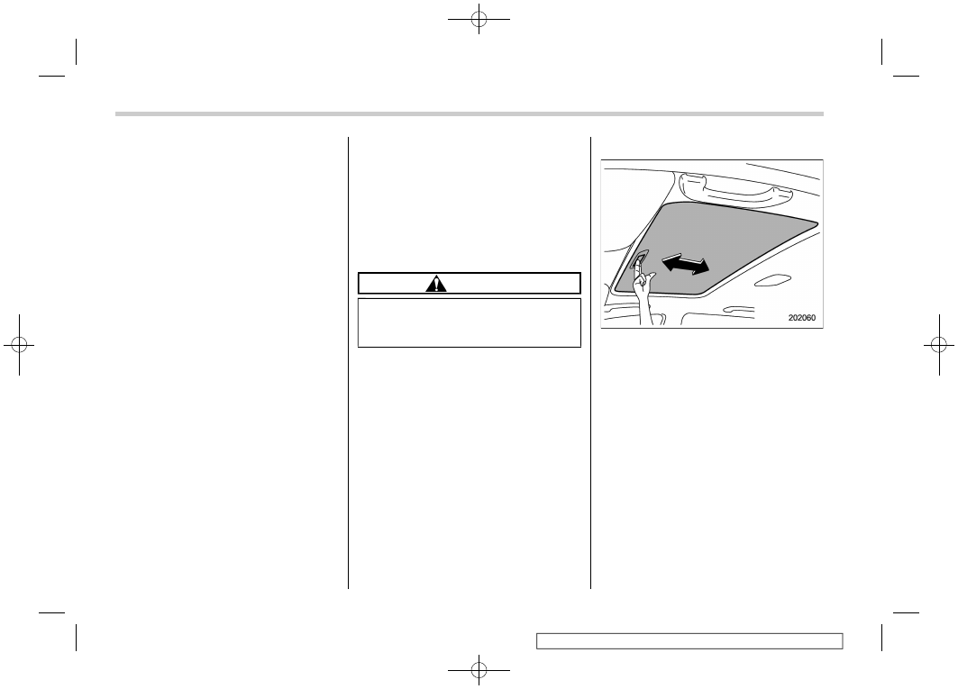
Sun shade
The sun shade can be slid forward or
backward by hand while the moonroof is
closed.
If the moonroof is opened, the sun shade
also moves back.
Moonroof
150