Subaru Legacy IV (2008 year). Manual - part 979


  Index      Subaru     Subaru Legacy IV - service repair manual 2008 year


Search            


Content   ..  977  978  979  980   ..


Subaru Legacy IV (2008 year). Manual - part 979


AC-19

General Description

HVAC SYSTEM (HEATER, VENTILATOR AND A/C)

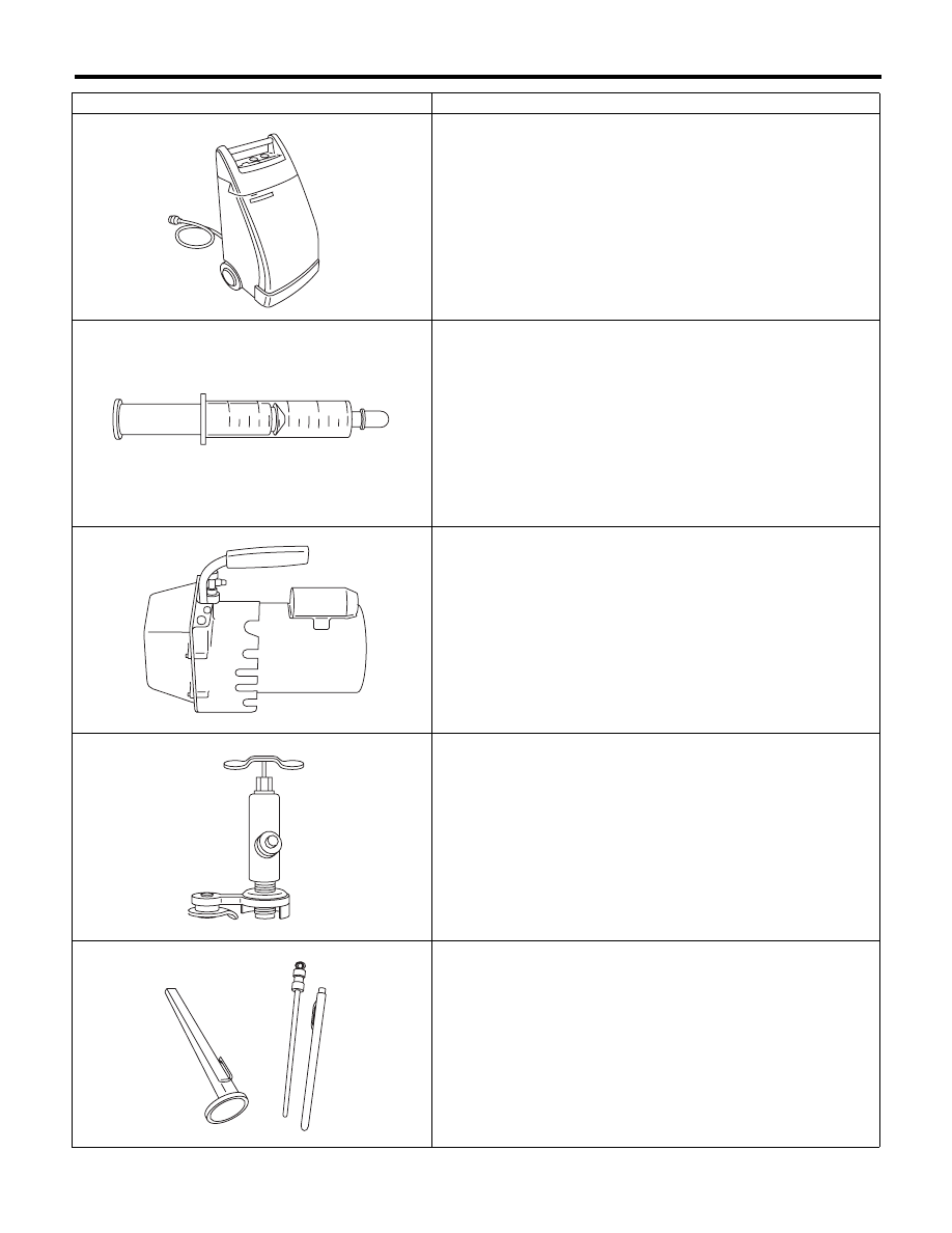
Refrigerant recovery system

REFRIGERANT RECOVERY SYSTEM is used for the recovery and 
recycling of A/C system refrigerant after contaminants and moisture 
have been removed from the refrigerant.

Syringe

A graduated plastic SYRINGE will be needed to add oil into the system 
again. A syringe can be available at a pharmacy or drug store.

Vacuum pump

VACUUM PUMP is necessary (for a good working condition), and is 
available either at a refrigerant supplier or an automotive equipment 
supplier.

Can tap

CAN TAP for the 397 g (14 oz.) can is available at an automotive 
equipment supplier.

Thermometer

A Pocket THERMOMETER is available either at a industrial hardware 
store or a refrigerant supplier.

ILLUSTRATION

Tools and Equipment

AC-00014

AC-00015

AC-00016

AC-00017

AC-00018

AC-20

General Description

HVAC SYSTEM (HEATER, VENTILATOR AND A/C)

Electronic leak detector

An ELECTRONIC LEAK DETECTOR can be available either at a spe-
cialty tool supplier or an A/C equipment supplier.

Weight scale

WEIGHT SCALE such as an electronic charging scale or a bath-
room scale with digital display will be needed, if a 13.6 kg (30 lb) refrig-
erant container is used.

ILLUSTRATION

Tools and Equipment

AC-00019

AC-00020

AC-21

Refrigerant Pressure with Manifold Gauge Set

HVAC SYSTEM (HEATER, VENTILATOR AND A/C)

2. Refrigerant Pressure with Manifold Gauge Set

A: PROCEDURE

1) Place the vehicle in the shade and windless condition.
2) Connect the manifold gauge set.
3) Open the front windows and close all doors.
4) Open the front hood.
5) Increase the engine to 1,500 rpm.
6) Turn on the A/C switch.
7) Turn the temperature control switch to MAX COOL.
8) Put in RECIRC position.
9) Turn the blower control switch to HI.
10) Read the gauge.

Standard:

Low: 127 — 196 kPa (1.3 — 2.0 kg/cm

2

, 18 — 28 psi)

High: 1,471 — 1,667 kPa (15 — 17 kg/cm

2

, 213 — 242 psi)

Ambient temperature: 30 — 35°C (86 — 95°F)

B: INSPECTION

Symptom

Probable cause

Repair order

High-pressure side is unusually high.

• Defective condenser fan motor
• Clogged condenser fin
• Too much refrigerant
• Air inside the system
• Defective receiver dryer

• Replace the fan motor.
• Clean the condenser fin.
• Discharge refrigerant.
• Replace the receiver dryer.
• After evacuating again, charge an 
appropriate amount of refrigerant.

High-pressure side is unusually low.

• Defective compressor
• Not enough refrigerant
• Clogged expansion valve
• Expansion valve frozen temporarily by 
moisture.

• Replace the compressor.
• Check for leaks.
• Replace the expansion valve.
• Fully evacuate the expansion valve.

Low-pressure side is unusually high.

• Defective compressor
• Defective expansion valve
• Too much refrigerant

• Replace the compressor.
• Replace the expansion valve.
• Discharge refrigerant.

Low-pressure side is unusually low.

• Not enough refrigerant
• Clogged expansion valve
• Expansion valve frozen temporarily by 
moisture.
• Saturated receiver dryer

• Check for leaks.
• Replace the expansion valve.
• Replace the receiver dryer.

AC-22

Refrigerant Recovery Procedure

HVAC SYSTEM (HEATER, VENTILATOR AND A/C)

3. Refrigerant Recovery 

Procedure

A: PROCEDURE

CAUTION:
• During operation, be sure to wear protective
goggles and protective gloves.
• Connect the refrigerant recovery system with
the manifold gauge set to discharge the refrig-
erant from the A/C system and recycle the gas.
• When recycling the discharged refrigerant,
keep service cans on hand. Because the recov-
ery rate with the recovery system is approx.
90%, service cans are necessary to charge the
refrigerant.
• Follow the detailed operation procedure de-
scribed in the operation manual attached to the
refrigerant recovery system.
1) Perform compressor oil return operation. <Ref.
to AC-27, PROCEDURE, Compressor Oil.>
2) Stop the engine.
3) Make sure the valves on low/high pressure sides
of manifold gauge set are fully closed.

4) Install the low/high pressure hoses to the service
ports on the low/high pressure sides of the vehicle
respectively.

5) Connect the center hose to the refrigerant recov-
ery system.
6) Follow the operation manual to activate the re-
frigerant recovery system.

L: Low pressure gauge

H: High-pressure gauge

(1) Low pressure valve

(2) Vacuum pump valve

(3) High pressure valve

(4) For low pressure

(5) For vacuum pump

(6) For high pressure

AC-00146

(2)

(4)

(5)

(6)

(3)

(3)

(2)

(1)

H

L

(1)

(1) Low-pressure side service port

(2) High-pressure side service port

(3) Close

AC-00147

(3)

(2)

(1)


Content   ..  977  978  979  980   ..