Subaru Legacy IV (2008 year). Manual - part 980


  Index      Subaru     Subaru Legacy IV - service repair manual 2008 year


Search            


Content   ..  978  979  980  981   ..


Subaru Legacy IV (2008 year). Manual - part 980


AC-23

Refrigerant Charging Procedure

HVAC SYSTEM (HEATER, VENTILATOR AND A/C)

4. Refrigerant Charging 

Procedure

A: PROCEDURE

CAUTION:
• While working, make sure to wear protective
goggles and gloves.
• Air in the cycle can cause insufficient air con-
ditioning, and water in the cycle can cause
clogging in the cycle (icing) and rust. To re-
move this air and water content, use a vacuum
pump to perform evacuation of the system be-
fore filling with refrigerant. By making the in-
side of the cycle a vacuum, the water content
will evaporate even at atmospheric tempera-
tures, and can be removed.
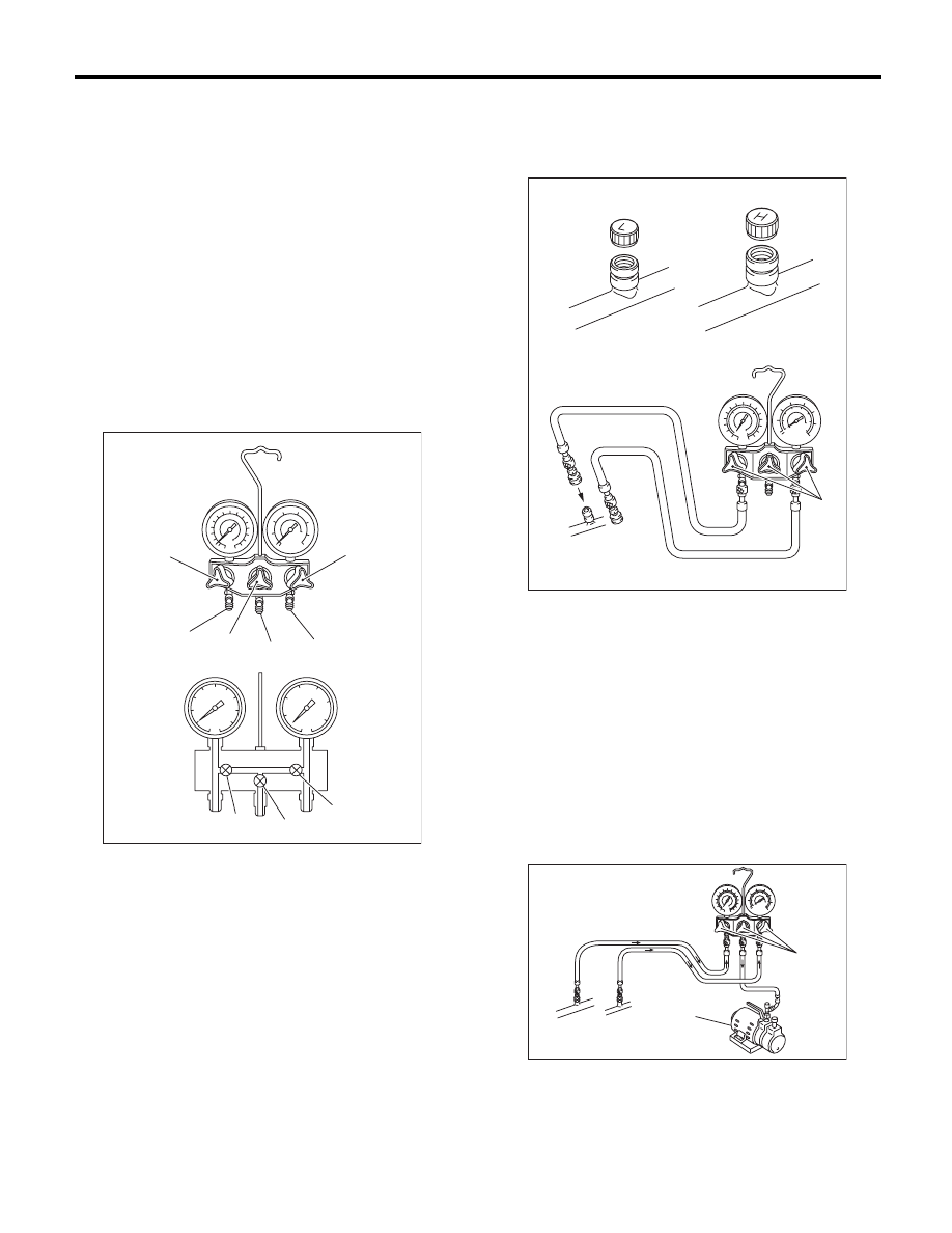
1) Close all valves of the manifold gauge.

2) Attach the low pressure side and high pressure
side hoses to the vehicle service port.

CAUTION:
Confirm that the connection is secure.

3) Connect the center manifold hose of the mani-
fold gauge to the vacuum pump.
4) Operate the vacuum pump and open the low
pressure and high pressure side valves. Next, open
the center manifold hose valve, and begin evacua-
tion.

CAUTION:
Make sure to perform evacuation using a vacu-
um pump.

L: Low pressure gauge

H: High-pressure gauge

(1) Low pressure valve

(2) Vacuum pump valve

(3) High pressure valve

(4) For low pressure

(5) For vacuum pump

(6) For high pressure

AC-00146

(2)

(4)

(5)

(6)

(3)

(3)

(2)

(1)

H

L

(1)

(1) Low-pressure side service port

(2) High-pressure side service port

(3) Close

(1) Vacuum pump

(2) Open

AC-00147

(3)

(2)

(1)

AC-00148

(1)

(2)

AC-24

Refrigerant Charging Procedure

HVAC SYSTEM (HEATER, VENTILATOR AND A/C)

5) After performing evacuation for over 5 minutes,
when the low pressure gauge needle reaches
above –100.0 kPa (–750 mmHg, –29.5 inHg), close
the center manifold hose valve, and stop the vacu-
um pump.
6) Leave alone for 5 to 10 minutes after closing the
low pressure side and high pressure side valves,
and check whether there is any change in the low
pressure gauge needle indication. If there is a
change, this indicates a leak. Check the pipe and
hose connections, and check the location with the
problem. In this case, repeat again from step 1).
7) If there is no leakage, continue evacuation for an
additional 20 to 30 minutes.
8) Close all valves, and stop the vacuum pump.
9) Follow the can tap operation manual, and attach
the refrigerant can.

10) Disconnect the center manifold hose from the
vacuum pump, and connect the hose to the tap
valve.
11) When a 13.6 kg (30 lb) refrigerant container is
used, measure the amount of refrigerant with a re-
frigerant charging scale, and connect with the cen-
ter manifold hose.

12) Open the valve on the HFC-134a source.

13) Loosen the center manifold hose connection on
the manifold gauge for a few seconds (if there is a
purge valve on the manifold gauge push this in-
stead) to allow the air in the center manifold hose to
escape using the refrigerant pressure.

14) Open the high pressure side and low pressure
side valves of the manifold gauge to fill with refrig-
erant.

CAUTION:
When filling with the engine running,  do not
open the high pressure side valve. Always fill
from the low pressure side.

15) When the gauge needle indicates approxi-
mately 200 kPa (1,500 mmHg, 59.1 inHg), close all
valves.
16) Using a leak tester, check for refrigerant leaks
in the system.
17) After checking that there is no refrigerant leaks,
fill with refrigerant up to the specified amount.
18) If the HFC-134a supply container becomes
empty, close all valves, and close the can tap valve
to replace the empty container. After replacing with
a new HFC-134a supply container, perform air
purge, and resume the filling operation.
19) If the refrigerant filling efficiency drops, close all
valves.
20) Check that both the low pressure and high
pressure valves are closed. Start the engine with
the A/C switch OFF.
21) To prevent damage to the compressor, push
the A/C switch ON-OFF quickly a few times.

(1) Tap valve

(2) To center manifold hose

(1) Refrigerant container (HFC-134a)

(2) Weight scale

AC-00214

(1)

(2)

AC-00215

(1)

(2)

(1) Open

(2) Open

AC-00216

(1)

(2)

AC-00217

AC-25

Refrigerant Charging Procedure

HVAC SYSTEM (HEATER, VENTILATOR AND A/C)

22) Set up the vehicle to the following status:

CAUTION:
When filling with the engine running, do not
open the high pressure side valve.
Always fill from the low pressure side valve.
• A/C switch ON
• Engine running at 1,500 rpm
• Blower speed setting to “HI”
• Temperature setting to “MAX COOL”
• Air inlet setting to “RECIRC”
• Window open
23) Open the low pressure side valve and fill with
refrigerant up to the specified amount.
24) After filling with refrigerant, close all valves and
disconnect the hose from the service port.
25) Attach the cap of the service port.

AC-26

Refrigerant Leak Check

HVAC SYSTEM (HEATER, VENTILATOR AND A/C)

5. Refrigerant Leak Check

A: INSPECTION

1) Operate the A/C system for approx. 10 minutes,
and check that the high-side pressure shows at
least 690 kPa (7.03 kg/cm

2

, 100 psi). Then stop the

engine to start the leak test.
2) Starting from the connection between high-pres-
sure pipe and evaporator, check the system for
leaks along the high-pressure side through the
compressor. The following items must be checked
thoroughly.
3) Check the joint and seam between pressure
switch (dual switch) and high-pressure pipe.
4) Check the connections between condenser and
pipes, and welded joints on the condenser.
The leak tester may detect the oil on the condenser
fins as a leak.
5) Check the joint between compressor and hoses.
6) Check the machined area of the compressor and
other joints on the compressor.
7) Check the compressor shaft seal at the area
near the center of compressor clutch pulley.
Shaft seals may show a slight amount of leakage,
about 3 g (0.1 oz) per year. This is not a problem.
8) Starting from the connection between low-pres-
sure pipe and evaporator, check the system for
leakage along the low-pressure side through the
compressor. The following items must be checked
thoroughly.
• Connection between 2 parts
• Connection between pipe and plate

9) Visually check the rubber area of the flexible
hose for cracks.
Check the entire length of the flexible hose, espe-
cially the connection with the metal hose end.

CAUTION:
Carefully check the external surface of hoses
and pipes at approx. 25 mm (0.98 in) per second.

10) Disconnect the drain hose from the heater
case, and check the hose end for at least 10 sec-
onds.
After the test is finished, reconnect the drain hose.
11) Turn the ignition key to the ON position, and
run the blower at high speed for approx. 1 minute.
Stop the blower and check the ventilation grille on
the instrument panel. While moving the tester clos-
er to the grille, run the blower for 1 or 2 seconds,
then stop it. Check the grille at that position for at
least 10 seconds.

12) Check the valve in the service port.
13) Visually check the rubber seal in the service
port cap.

AC-00035

(A) Flexible hose

AC-00036

(A)

AC-00037

AC-00038


Content   ..  978  979  980  981   ..