Subaru Legacy IV (2008 year). Manual - part 895


  Index      Subaru     Subaru Legacy IV - service repair manual 2008 year


Search            


Content   ..  893  894  895  896   ..


Subaru Legacy IV (2008 year). Manual - part 895


DS-25

Front Drive Shaft

DRIVE SHAFT SYSTEM

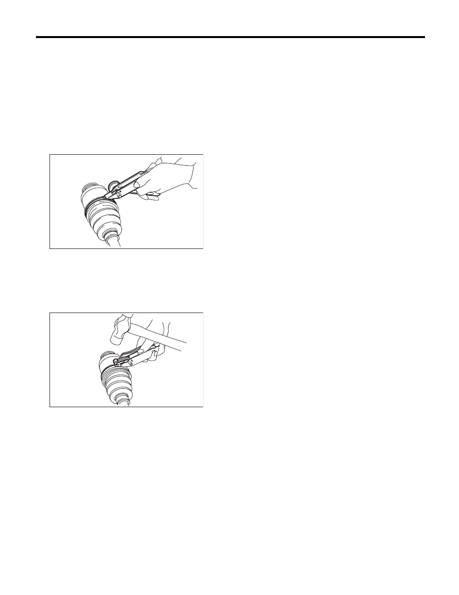
11) Put a new band through the clip and wind twice
in the band groove of the boot.
12) Pinch the end of band with pliers. Hold the clip
and tighten securely.

NOTE:
When tightening boot, use care so that the air with-
in the boot is appropriate.
13) Tighten the band using the ST.
ST

925091000

BAND TIGHTENING TOOL

NOTE:
Tighten the band until it cannot be moved by hand.

14) Tap the clip with the punch provided at the end
of the ST.
ST

925091000

BAND TIGHTENING TOOL

CAUTION:
Tap to an extent that the boot underneath is not
damaged.

15) Cut off the band with an allowance of about 10
mm (0.39 in) left from the clip and bend this allow-
ance over the clip.

CAUTION:
Make sure that the end of the band is in close
contact with clip.
16) Extend and retract the PTJ to provide equal
grease coating.

E: INSPECTION

Check the removed parts for damage, wear, corro-
sion etc. If faulty, repair or replace.
• PTJ (pillow tripod joint)
Check for seizure, corrosion, damage, wear and
excessive play.
• EBJ (high-efficiency compact ball fixed joint)
Check for seizure, corrosion, damage and exces-
sive play.
• Shaft
Check for excessive bending, twisting, damage
and wear.
• Boot
Check for wear, warping, breakage and scratches.
• Grease
Check for discoloration and fluidity.

DS-00132

DS-00133

DS-26

Rear Drive Shaft

DRIVE SHAFT SYSTEM

7. Rear Drive Shaft

A: REMOVAL

1) Disconnect the ground cable from battery.
2) Lift up the vehicle, and then remove the rear
wheels.
3) Lift the crimped section of axle nut.

4) While applying the parking brake, remove the
axle nut using a socket wrench.

CAUTION:
Remove the wheel before loosening the axle
nut. Failure to follow this rule may damage the
wheel bearings.
5) Remove the rear differential assembly.
• T-type
<Ref. to DI-30, REMOVAL, Rear Differential (T-
type).>
• VA-type
<Ref. to DI-56, REMOVAL, Rear Differential (VA-
type).>
6) Remove the axle nut and rear drive shaft. If it is
hard to remove, use ST1 and ST2.
ST1

926470000

AXLE SHAFT PULLER

ST2

927140000

AXLE SHAFT PULLER PLATE

CAUTION:
• Do not hammer drive shaft when removing.
• Do not damage the oil seal and magnetic en-
coder.

B: INSTALLATION

1) Insert the BJ or EBJ into the rear hub splines.

CAUTION:
• Be careful not to damage the magnetic en-
coder.
• Do not get closer the tool which charged
magnetism to magnetic encoder.

2) Draw the rear drive shaft into specified position.

CAUTION:
Do not hammer drive shaft when installing it.
3) Tighten the axle nut temporarily.
4) Install the rear differential assembly.
• T-type
<Ref. to DI-32, INSTALLATION, Rear Differential
(T-type).>
• VA-type
<Ref. to DI-58, INSTALLATION, Rear Differential
(VA-type).>
5) While applying the parking brake and depress-
ing the brake pedal, tighten a new axle nut to the
specified torque and lock it securely.

Tightening torque:

240 N·m (24.5 kgf-m, 177 ft-lb)

CAUTION:
• Install the wheel after installation of axle nut.
Failure to follow this rule may damage the
wheel bearing.
• Be sure to tighten the axle nut to specified
torque. Do not overtighten it as this may dam-
age the wheel bearing.

DS-00038

DS-00122

ST2

ST1

(1) Magnetic encoder

(2) Rear hub unit bearing

DS-00251

(2)

(1)

DS-27

Rear Drive Shaft

DRIVE SHAFT SYSTEM

6) Lock the axle nut securely.

7) Install the wheel.

Tightening torque:

120 N·m (12.2 kgf-m, 88.5 ft-lb)

C: DISASSEMBLY

1) Straighten the bent claw at the larger end of the
DOJ boot.
2) Loosen the band by means of screwdriver or pli-
ers.

CAUTION:
Be careful not to damage the boot.

3) Remove the boot band on the small end of DOJ
boot in the same manner.
4) Remove the larger end of DOJ boot from DOJ
outer race.
5) Pry and remove the round circlip at the neck of
DOJ outer race with a screwdriver.

6) Take out the DOJ outer race from the shaft as-
sembly.

7) Wipe off the grease and take out the ball bear-
ings.

CAUTION:
The grease is a special grease (grease for con-
stant velocity joints). Do not mix with other
greases.

NOTE:
Disassemble exercising care not to lose balls (6
pcs).

8) To remove the cage from inner race, turn the
cage by a half pitch to the track groove of inner race
and shift the cage.
9) Using pliers, remove the snap ring fixing the in-
ner race to the shaft.
10) Take out the DOJ inner race.
11) Take off the DOJ cage from shaft and remove
the DOJ boot.

CAUTION:
Be sure to wrap shaft splines with vinyl tape to
prevent boot from scratches.
12) Remove the BJ boot or EBJ boot in the same
procedure as the DOJ boot.

NOTE:
Further disassembly of axle is impossible because
the BJ and EBJ cannot be disassembled.

DS-00048

DS-00124

DS-00125

(A) Outer race

(B) Grease

DS-00126

(B)

(A)

DS-28

Rear Drive Shaft

DRIVE SHAFT SYSTEM

D: ASSEMBLY

NOTE:
Use specified grease.

BJ, EBJ side:

NKG106

DOJ side:

NKG205

1) Install the BJ or EBJ boot in specified position,
and fill it with 60 to 70 g (2.12 to 2.47 oz.) of speci-
fied grease.
2) Place the DOJ boot at the center of shaft.

CAUTION:
Be sure to wrap shaft splines with vinyl tape to
prevent boot from scratches.
3) Insert the DOJ cage onto shaft.

NOTE:
Insert the cage with the cutout portion facing the
shaft end, since the cage has an orientation.

4) Install the DOJ inner race on shaft and fix the
snap ring in place with pliers.

NOTE:
Confirm that the snap ring is completely fitted in the
shaft groove.

5) Install the cage to inner race fixed upon shaft.

NOTE:
Fit the cage with the protruding section aligned with
the track on the inner race, and turn by a half pitch.

6) Fill 80 to 90 g (2.82 to 3.17 oz) of specified
grease into the inner side of the DOJ outer race.
7) Apply a thin coat of specified grease to the cage
pocket and six ball bearings.
8) Insert the six ball bearings into the cage pocket.
9) Align the outer race track and ball positions, and
place the shaft, inner race, cage and ball bearings
in the original positions, and then fix outer race in
place.

(A) Cage

(B) Cutout portion

DS-00395

(B)

(A)

DS-00128

(A) Inner race

(B) Cage

(A) Outer race

(B) Grease

(B)

(A)

DS-00129

DS-00126

(B)

(A)


Content   ..  893  894  895  896   ..