Subaru Legacy IV (2008 year). Manual - part 871
DI-33
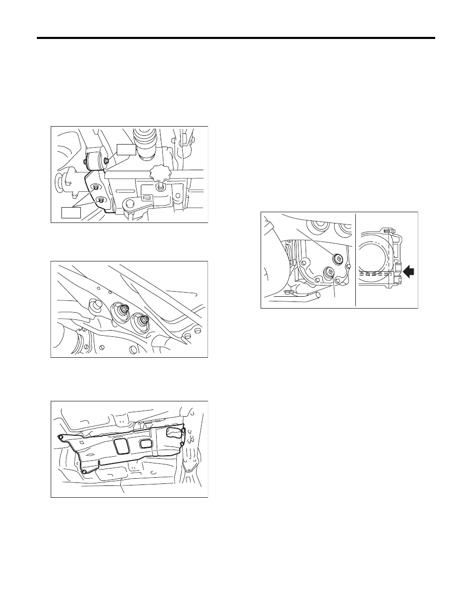
Rear Differential (T-type)
DIFFERENTIALS
10) Remove the band from rear differential. Lift up
the rear differential until the rear differential is sep-
arated from the transmission jack.
11) Install the rear differential front member with a
new self-locking nut.
Tightening torque:
T1: 50 N·m (5.1 kgf-m, 36.9 ft-lb)
T2: 110 N·m (11.2 kgf-m, 81.1 ft-lb)
12) Tighten the self-locking nut.
Tightening torque:
70 N·m (7.1 kgf-m, 51.6 ft-lb)
13) Lower the transmission jack.
14) Install the propeller shaft. <Ref. to DS-11, IN-
STALLATION, Propeller Shaft.>
15) Install the heat shield cover.
16) Install the rear exhaust pipe and muffler.
• 2.5 L SOHC non-turbo model
<Ref. to EX(H4SO)-8, INSTALLATION, Rear Ex-
haust Pipe.> <Ref. to EX(H4SO)-10, INSTALLA-
TION, Muffler.>
• 2.5 L DOHC turbo model
<Ref. to EX(H4DOTC)-13, INSTALLATION, Rear
Exhaust Pipe.> <Ref. to EX(H4DOTC)-14, IN-
STALLATION, Muffler.>
17) After installing the rear differential carrier to the
vehicle, remove the filler plug, and refill with gear oil
up to the lower lip of the plug hole.
Oil capacity:
Except for GT spec. B 6MT model:
0.8
2
(0.8 US qt, 0.7 Imp qt)
GT spec. B 6MT model:
1.0
2
(1.1 US qt, 0.9 Imp qt)
18) Tighten the filler plug.
NOTE:
• Apply liquid gasket to the filler plug. (Except for
GT spec. B 6MT model)
Liquid gasket:
THREE BOND 1105 (Part No. 004403010) or
equivalent
• Use a new gasket. (GT spec. B 6MT model)
Tightening torque:
Except for GT spec. B 6MT model:
49 N·m (5.0 kgf-m, 36.1 ft-lb)
GT spec. B 6MT model:
60 N·m (6.1 kgf-m, 44.3 ft-lb)
19) Hereafter, install in the reverse order of remov-
al.
DI-00284
T2
T1
DI-00269
AT-01331
(A) Filler plug
(B) Oil drain plug
DI-00285
(A)
(B)