Subaru Legacy IV (2008 year). Manual - part 855


  Index      Subaru     Subaru Legacy IV - service repair manual 2008 year


Search            


Content   ..  853  854  855  856   ..


Subaru Legacy IV (2008 year). Manual - part 855


TPM(diag)-6

Control Module I/O Signal

TIRE PRESSURE MONITORING SYSTEM (DIAGNOSTICS)

4. Control Module I/O Signal

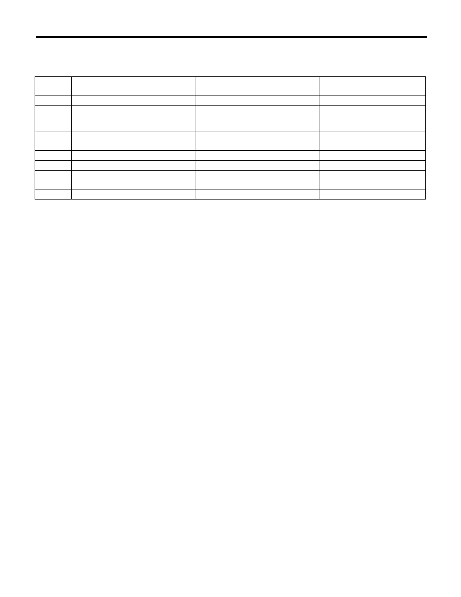
A: ELECTRICAL SPECIFICATION

Terminal 

No.

Measured value

Measuring condition

Remarks

1

Select monitor communication

Serial communication

 — 

2

Tire pressure warning light output

Illuminate when malfunction occurs, or 
tire pressure decreases

System failure: blinks 25 times 

o

illuminates
Tire pressure decreases: turns on

4

Speed sensor signal

While driving (Pulse signal)

Change according to vehicle 
speed

5

Ignition power supply

IG switch ON (Battery voltage)

 — 

6

Battery power supply

Battery voltage

Always

8

Body integrated unit (Hazard output 
signal)

 — 

When hazard turns on.

9

GND

0 V (Always)

Always

TPM(diag)-7

Control Module I/O Signal

TIRE PRESSURE MONITORING SYSTEM (DIAGNOSTICS)

B: WIRING DIAGRAM

(1)

Battery power supply

(4)

Antenna

(8)

Vehicle speed signal

(2)

Ignition power supply

(5)

GND

(9)

Subaru Select Monitor

(3)

Tire pressure monitoring control 
module

(6)

Transmitter

(10)

Body integrated unit

(7)

Combination meter


TPM00005

(6)

(6)

(6)

(6)

(1)

(2)

(7)

(9)

(5)

(8)

(10)

(3)

6

5

4

8

2

1

9

(4)

1 2 3 4 5 6
7 8 9 10 11 12

TPM(diag)-8

Subaru Select Monitor

TIRE PRESSURE MONITORING SYSTEM (DIAGNOSTICS)

5. Subaru Select Monitor

A: OPERATION

1. READ DIAGNOSTIC TROUBLE CODE 
(DTC)

1) Prepare the Subaru Select Monitor kit. <Ref. to
TPM(diag)-4, SPECIAL TOOL, PREPARATION
TOOL, General Description.>
2) Connect the diagnosis cable to Subaru Select
Monitor.
3) Connect the Subaru Select Monitor to data link
connector.

(1) Data link connector is located in the lower
portion of instrument panel (on the driver’s
side).

(2) Connect the diagnosis cable to data link
connector.

CAUTION:
Do not connect scan tools other than the Suba-
ru Select Monitor.
4) Turn the ignition switch to ON (engine OFF) and
run the Subaru Select Monitor.
5) On the «Main Menu» display, select the {Each
System Check}.
6) On the «System Selection Menu» display, select
the {Tire pressure monitor}.
7) After {Model Year} is displayed, select [OK].

8) On the «Tire pressure monitor diagnosis» dis-
play, select the {Diagnostic Code(s) Display}.

NOTE:
• For detailed operation procedures, refer to the
“PC application help for Subaru Select Monitor”.
• For details concerning DTCs, refer to List of Di-
agnostic Trouble Code (DTC). <Ref. to TPM(diag)-
26, List of Diagnostic Trouble Code (DTC).>
• Display all the DTCs detected.
• If a particular DTC is not properly stored in mem-
ory (due to a voltage drop of the tire air pressure
monitor control module power supply, etc.) when a
problem occurs, a DTC suffixed with a question
mark will appears on the Subaru Select Monitor
display. This shows it may be an unreliable read-
ing.
9) If communication is not possible between the tire
pressure monitoring control module and the Suba-
ru Select Monitor, check the communication circuit.
<Ref. to TPM(diag)-11, COMMUNICATION FOR
INITIALIZING IMPOSSIBLE, INSPECTION, Suba-
ru Select Monitor.>
10) When DTC is not displayed, check the indicator
circuit and communication circuit. <Ref. to TPM(di-
ag)-14, WITHOUT DTC, INSPECTION, Subaru
Select Monitor.>

(1) Data link connector

ABS00465

(1)

TPM(diag)-9

Subaru Select Monitor

TIRE PRESSURE MONITORING SYSTEM (DIAGNOSTICS)

2. DATA DISPLAY

1) On the «Main Menu» display, select the {Each System Check}.
2) On the «System Selection Menu» display, select the {Tire pressure monitor}.
3) After the {Tire pressure monitor} is displayed, select [OK].
4) On the «Tire pressure monitor diagnosis» display, select the {Data Display}, and then necessary data will
be displayed.
• A list of the support data is shown in the following table.

3. CLEAR MEMORY

1) On the «Main Menu» display, select the {2. Each
System Check}.
2) On the «System Selection Menu» display, select
the {Tire pressure monitor}.
3) After the {Tire pressure monitor} is displayed,
select [OK].
4) On the «Tire pressure monitor diagnosis» dis-
play, select the {Clearing Memory}.
5) When “Done” and “Turn off the ignition switch.”
are shown on the display screen, end the Subaru
Select Monitor and turn the ignition switch to OFF.

NOTE:
For detailed operation procedures, refer to the “PC
application help for Subaru Select Monitor”.

1. Data monitor (Analog)

Display

Contents to be displayed

Unit of measure

Tire 1 FN code

LEARN, LOW BAT, OFF, WAKE, RE ME, NOR-
MAL

LEARN: Transmitted transmitter ID using the transmit-
ter registration tool
LOW BAT: Transmitter battery voltage running low
OFF: Transmitter function stops (no data transmission)
RE ME: Tire air changes 

r8.4 kPa

WAKE: When data transmission is started from a 
stopped state.
NORMAL: Conditions other than above

Tire 2 FN code

Tire 3 FN code

Tire 4 FN code

Tire 1 air pressure

Value converted to tire pressure from data deliv-
ered from transmitter is displayed.
(The figure may differ from the actual measured 
values.)

kPa, psig, mmHg, inHg

Tire 2 air pressure

kPa, psig, mmHg, inHg

Tire 3 air pressure

kPa, psig, mmHg, inHg

Tire 4 air pressure

kPa, psig, mmHg, inHg

Vehicle Speed

Vehicle speed signal which is input in control mod-
ule.

km/h, MPH

Pressure warning

Threshold where tire pressure warning light illumi-
nates

kPa, psig, mmHg, inHg

Return pressure

Threshold where tire pressure warning light goes 
out

kPa, psig, mmHg, inHg


Content   ..  853  854  855  856   ..