Subaru Legacy IV (2008 year). Manual - part 825
6MT-113
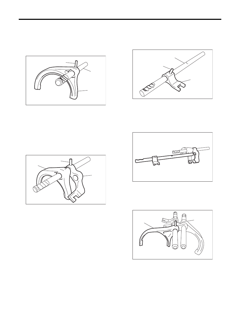
Shifter Fork and Rod
MANUAL TRANSMISSION AND DIFFERENTIAL
2. 1ST-2ND, 3RD-4TH SHIFTER FORK
1) Using the ST, install the 1st-2nd shifter fork.
ST
398791700
REMOVER
NOTE:
Make sure that the 1st-2nd shifter fork and rod are
installed in the correct direction.
2) Using the ST, install the 1st-2nd shifter arm.
ST
398791700
REMOVER
NOTE:
Make sure that the 1st-2nd shifter arm and fork are
installed in the correct direction.
3) Using the ST, install the 3rd-4th shifter arm.
ST
398791700
REMOVER
NOTE:
Make sure that the 3rd-4th shifter arm and rod are
installed in the correct direction.
4) Attach the 3rd-4th fork rod to the 1st-2nd shifter
arm.
5) Using the ST, install the 3rd-4th shifter fork.
ST
398791700
REMOVER
NOTE:
Make sure that the 3rd-4th shifter fork is installed in
the correct direction.
(A) 1st-2nd shifter fork
(B) 1st-2nd shifter rod
(C) Spring pin
(A) 1st-2nd shifter fork
(B) 1st-2nd shifter arm
(C) Spring pin
MT-00693
(C)
(B)
(A)
MT-00694
(C)
(B)
(A)
(A) 3rd-4th shifter rod
(B) 3rd-4th shifter arm
(C) Spring pin
(A) 3rd-4th shifter fork
(B) Spring pin
MT-00695
(C)
(B)
(A)
MT-00696
MT-01737
(B)
(A)