Subaru Legacy IV (2008 year). Manual - part 824


  Index      Subaru     Subaru Legacy IV - service repair manual 2008 year


Search            


Content   ..  822  823  824  825   ..


Subaru Legacy IV (2008 year). Manual - part 824


6MT-109

Front Differential Assembly

MANUAL TRANSMISSION AND DIFFERENTIAL

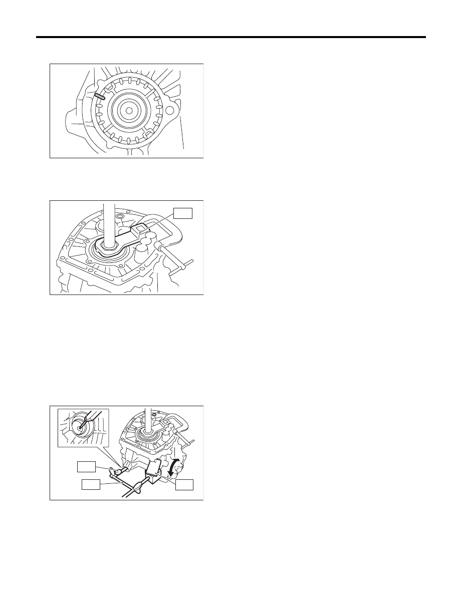
6) Mark the mating positions of the left and right
side retainers and the clutch housing.

7) Turn the back side retainer LH by 3 notches, and
screw in the side retainer RH by 3 notches.
8) Use the ST to fix the drive pinion shaft in place.
ST

18621AA000

ADAPTER WRENCH

9) Install the SUBARU genuine axle shaft to the
front differential left and right sides.
Part No.

38415AA000

Axle shaft

10) After turning the drive pinion shaft several
turns, use the ST to measure the hypoid gear back-
lash.
ST1

498255400

PLATE

ST2

498247001

MAGNET BASE

ST3

498247100

DIAL GAUGE

Hypoid gear backlash:

0.13 — 0.18 mm (0.0051 — 0.0071 in)

11) If the backlash is out of specified range, turn
the right and left side retainers to adjust.
12) Turn the RH side retainer by 1.25 notches or
more.

3. TOOTH CONTACT OF HYPOID GEAR

Regarding teeth contact conditions, refer to the
drive pinion section. <Ref. to 6MT-107, TOOTH
CONTACT OF HYPOID GEAR, INSPECTION,
Front Differential Assembly.>

MT-00658

ST

MT-00674

MT-00675

ST2

ST1

ST3

6MT-110

Shifter Fork and Rod

MANUAL TRANSMISSION AND DIFFERENTIAL

22.Shifter Fork and Rod

A: REMOVAL

1) Remove the manual transmission assembly
from the vehicle. <Ref. to 6MT-32, REMOVAL,
Manual Transmission Assembly.>
2) Prepare the transmission for overhaul. <Ref. to
6MT-37, Preparation for Overhaul.>
3) Remove the neutral position switch, back-up
light switch and harness. <Ref. to 6MT-41, RE-
MOVAL, Neutral Position Switch.> <Ref. to 6MT-
39, REMOVAL, Back-up Light Switch.>
4) Remove the extension case. <Ref. to 6MT-43,
REMOVAL, Extension Case.>
5) Remove the transfer driven gear. <Ref. to 6MT-
55, REMOVAL, Transfer Driven Gear.>
6) Remove the center differential. <Ref. to 6MT-57,
REMOVAL, Center Differential.>
7) Remove the transmission case. <Ref. to 6MT-
58, REMOVAL, Transmission Case.>
8) Remove the individual gear assemblies. <Ref. to
6MT-64, REMOVAL, Main Shaft Assembly.>

B: INSTALLATION

1) Install the individual gear assemblies all at once.
<Ref. to 6MT-65, INSTALLATION, Main Shaft As-
sembly.>
2) Install the transmission case. <Ref. to 6MT-60,
INSTALLATION, Transmission Case.>
3) Install the center differential. <Ref. to 6MT-57,
INSTALLATION, Center Differential.>
4) Install the transfer driven gear. <Ref. to 6MT-55,
INSTALLATION, Transfer Driven Gear.>
5) Install the extension case. <Ref. to 6MT-43, IN-
STALLATION, Extension Case.>
6) Install the neutral position switch, back-up light
switch and harness. <Ref. to 6MT-41, INSTALLA-
TION, Neutral Position Switch.> <Ref. to 6MT-39,
INSTALLATION, Back-up Light Switch.>
7) Install the manual transmission assembly to the
vehicle. <Ref. to 6MT-34, INSTALLATION, Manual
Transmission Assembly.>

C: DISASSEMBLY

NOTE:
Discard the removed spring pin, and replace with a
new part.

1. REVERSE SHIFTER FORK

1) Remove the reverse fork using the ST.
ST

398791700

REMOVER

2) Remove the reverse shifter arm using the ST.
ST

398791700

REMOVER

MT-00680

ST

MT-00681

ST

6MT-111

Shifter Fork and Rod

MANUAL TRANSMISSION AND DIFFERENTIAL

2. 1ST-2ND, 3RD-4TH SHIFTER FORK

1) Using the ST, remove the 3rd-4th shifter fork.
ST

398791700

REMOVER

2) Using the ST, remove the 3rd-4th shifter arm.
ST

398791700

REMOVER

3) Using the ST, remove the 1st-2nd shifter arm
and 1st-2nd shifter fork.
ST

398791700

REMOVER

3. 5TH-6TH SHIFTER FORK

1) Using the ST, remove the 5th-6th shifter fork.
ST

398791700

REMOVER

2) Using the ST, remove the 5th-6th shifter arm.
ST

398791700

REMOVER

4. SHIFTER ARM SHAFT

Remove the selector arm using the ST.
ST

398791700

REMOVER

(A) 1st-2nd shifter arm

(B) 1st-2nd shifter fork

MT-00682

ST

MT-00683

ST

MT-00684

(A)

(B)

MT-00685

ST

MT-00686

ST

MT-01095

ST

6MT-112

Shifter Fork and Rod

MANUAL TRANSMISSION AND DIFFERENTIAL

5. STRIKING ROD

1) Remove the reverse interlock block and the in-
terlock block from the striking rod.

2) Remove the reverse interlock arm using the ST.
ST

398791700

REMOVER

3) Remove the interlock arm using the ST.
ST

398791700

REMOVER

D: ASSEMBLY

1. REVERSE SHIFTER FORK

1) Using the ST, install the reverse fork.
ST

398791700

REMOVER

NOTE:
Confirm that the reverse fork and rod are installed
in the proper direction.

2) Using the ST, install the reverse arm.
ST

398791700

REMOVER

NOTE:
Confirm that the reverse arm and rod are installed
in the proper direction.

(A) Reverse interlock block

(B) Interlock block

(A) Reverse interlock arm

(B) Interlock arm

(A) Interlock arm

MT-00688

(A)

(B)

MT-00689

(A)

(B)

ST

MT-00690

(A)

ST

(A) Reverse fork

(B) Reverse rod

(C) Spring pin

(A) Reverse arm

(B) Reverse rod

(C) Spring pin

MT-00691

(C)

(B)

(A)

MT-00692

(C)

(B)

(A)


Content   ..  822  823  824  825   ..