Subaru Legacy IV (2008 year). Manual - part 741
5AT-88
Drive Pinion Shaft Assembly
AUTOMATIC TRANSMISSION
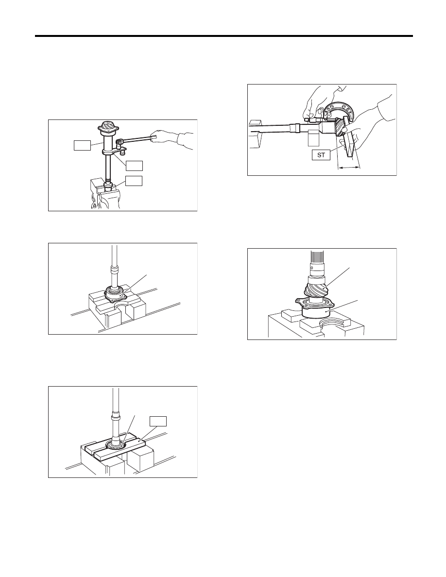
C: DISASSEMBLY
1) Flatten the lock nut tab, and then remove the
lock nut while holding the rear spline part of the
shaft using ST1 and ST2. Pull out the drive pinion
collar.
ST1
18667AA010
HOLDER
ST2
499787700
WRENCH
ST3
499787500
ADAPTER
2) Remove the O-ring.
3) Separate the roller bearing and outer race from
shaft using a press.
4) Separate the front roller bearing from the shaft
using a press and the ST.
ST
498517000
REPLACER
D: ASSEMBLY
1) Measure the dimension “A” of the drive pinion
shaft.
ST
398643600
GAUGE
2) Using a press, press-fit the new roller bearing
into the specified position.
NOTE:
If excessive force is applied to roller bearing, the
roller bearing will not turn easily.
3) After fitting a new O-ring to the shaft, attach the
drive pinion collar to the shaft.
(A) Outer race
(A) Front roller bearing
AT-00197
ST1
ST3
ST2
AT-00198
(A)
AT-00199
(A)
ST
A Measured value
(A) Drive pinion shaft
(B) Roller bearing
A
AT-00200
AT-00201
(B)
(A)