Subaru Legacy IV (2008 year). Manual - part 740
5AT-84
Oil Pump Cover
AUTOMATIC TRANSMISSION
C: DISASSEMBLY
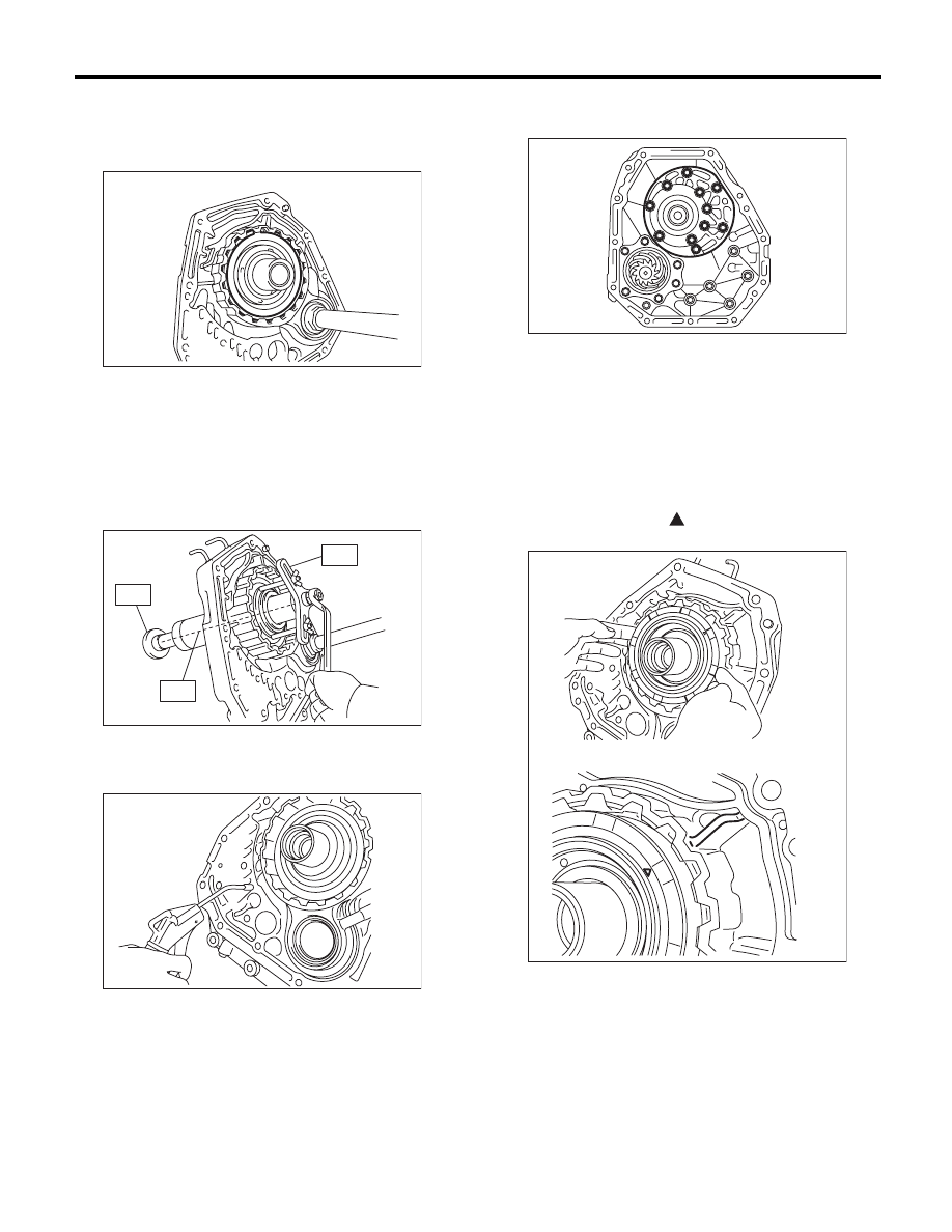
1. FRONT BRAKE
1) Remove the snap ring.
2) Remove the retainer plate, drive plate and driven
plate.
3) Using the ST1, ST2 and ST3, remove the snap
ring.
ST1
18762AA000
COMPRESSOR SPECIAL
TOOL
ST2
18765AA000
COMPRESSOR SUPPORT
ST3
18763AA000
COMPRESSOR SHAFT
4) Remove the retainer and return spring.
5) Remove the front brake piston using com-
pressed air.
6) Remove the D-ring from front brake piston.
2. OIL PUMP
1) Take out the oil pump housing.
2) Take out the oil pump body.
D: ASSEMBLY
1. FRONT BRAKE
1) Apply ATF to D-ring, and then install it to the
front brake piston.
2) Install the front brake piston to oil pump cover.
NOTE:
Install by aligning the “
” mark on front brake pis-
ton surface with the oil pump cover rib.
3) Install the retainer and return spring.
AT-01980
AT-01981
ST1
ST2
ST3
AT-02349
AT-01982
AT-02350