Subaru Legacy IV (2008 year). Manual - part 739
5AT-80
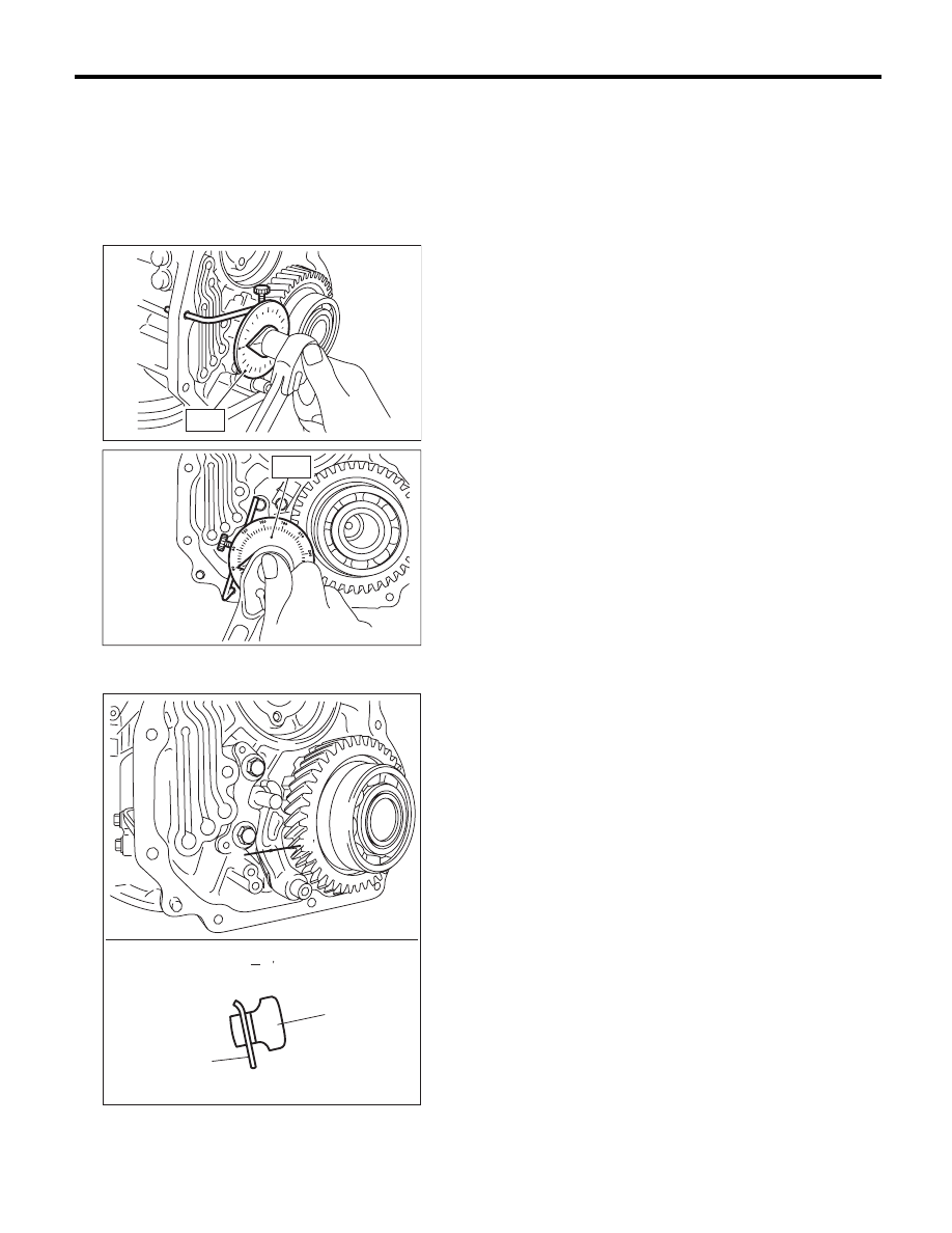
Parking Pawl
AUTOMATIC TRANSMISSION
4) Using the ST, tighten the bolts which tightened in
step 3) with specified angle.
Tightening angle:
17°
r
2°
ST
18854AA000
ANGLE GAUGE
NOTE:
Do not use extension as much as possible.
5) Make sure that the return spring is sticking out of
the parking pole hole.
6) Install the front vehicle speed sensor. <Ref. to
5AT-53, INSTALLATION, Front Vehicle Speed
Sensor.>
7) Install the center differential carrier. <Ref. to
5AT-77, INSTALLATION, Center Differential Carri-
er.>
8) Install the extension case. <Ref. to 5AT-68, IN-
STALLATION, Extension Case.>
9) Install the transmission assembly to the vehicle.
<Ref. to 5AT-43, INSTALLATION, Automatic
Transmission Assembly.>
C: INSPECTION
Make sure that the tab of parking pawl on reduction
driven gear is not worn or otherwise damaged.
(A) Parking pawl
(B) Return spring
AT-02071
ST
AT-02072
ST
AT-03370
B
(A)
(B)
B
B
B