Subaru Legacy IV (2008 year). Manual - part 685


  Index      Subaru     Subaru Legacy IV - service repair manual 2008 year


Search            


Content   ..  683  684  685  686   ..


Subaru Legacy IV (2008 year). Manual - part 685


4AT-88

Oil Pump Housing

AUTOMATIC TRANSMISSION

(3) If the depth and/or side clearance are not
within the specification, replace the oil pump ro-
tor assembly.

Measure the total end play and adjust it to be
within specifications. <Ref. to 4AT-88, AD-
JUSTMENT, Oil Pump Housing.>
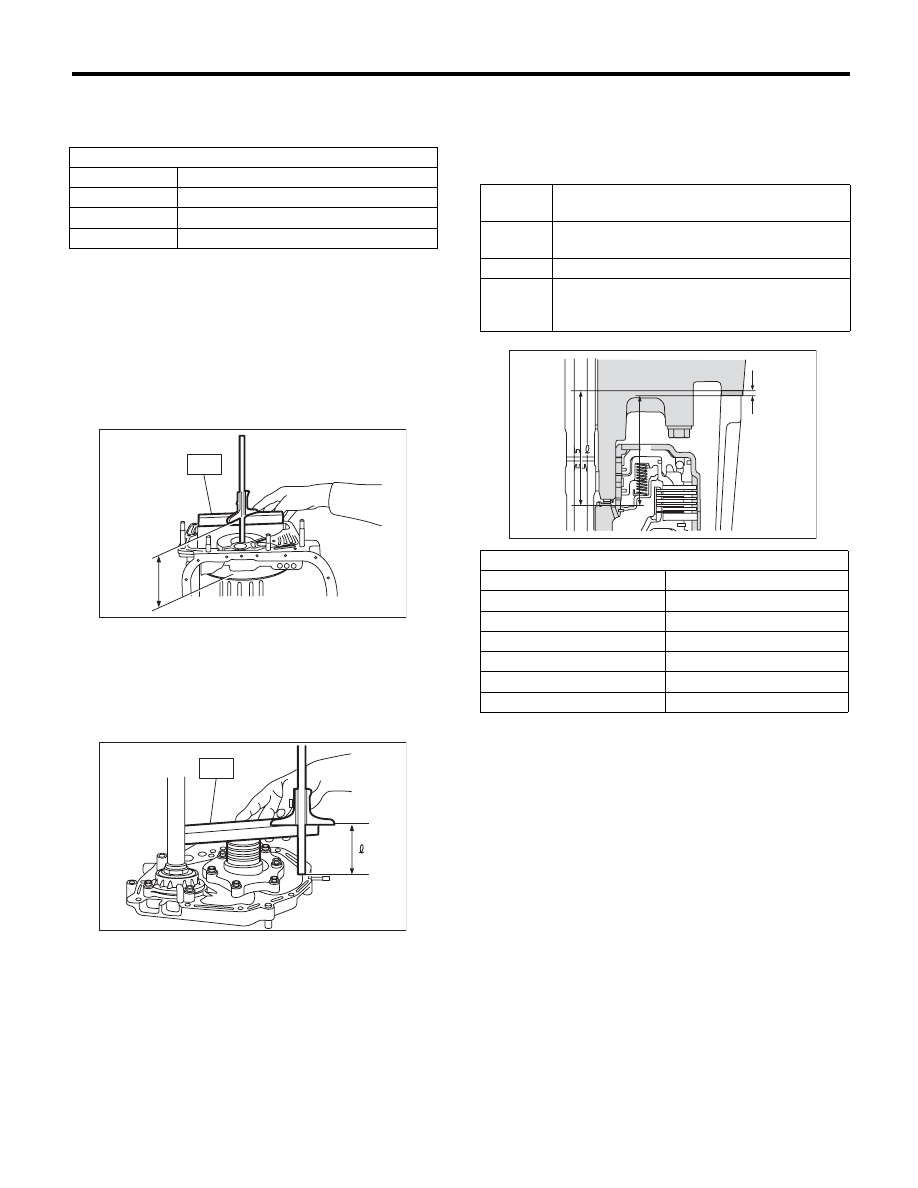
F: ADJUSTMENT

1) Using the ST, measure the length “L”, from the
mating surface of the transmission to the recessed
portion of the high clutch drum.
ST

398643600

GAUGE

2) Using the ST, measure the length “L” from the oil
pump housing mating surface to the top surface of
the oil pump cover with the thrust needle bearing.
ST

398643600

GAUGE

3) Calculation of total end play
Select a suitable bearing race from the table below
so that clearance C will be within 0.25 to 0.55 mm
(0.0098 to 0.0217 in).
C = (L + G) – 

2

4) After completing the total end play adjustment,
insert the bearing race into the high clutch race. Ap-
ply vaseline, and install the thrust needle bearing to
the oil pump cover.
5) After correctly installing the new gasket to the
case mating surface, carefully install the oil pump
housing assembly. Be careful to avoid hitting the
drive pinion against the inside of case.
6) Install both parts with dowel pins aligned. Make
sure there is no clearance at the mating surface.

Oil pump rotor assembly

Part No.

Thickness mm (in)

15008AA060

11.37 — 11.38 (0.4476 — 0.4480)

15008AA070

11.38 — 11.39 (0.4480 — 0.4484)

15008AA080

11.39 — 11.40 (0.4484 — 0.4488)

L Measured value

2 Measured value

AT-00194

L

ST

AT-00195

ST

C

Clearance between concave section of high 
clutch and end of clutch drum support

L

Length from case mating surface to the concave 
portion of the high clutch

G

Gasket thickness [0.28 mm (0.0110 in)]

2

Height from the oil pump housing mating sur-
face to the upper surface of the oil pump cover 
with the thrust needle bearing.

Thrust needle bearing

Part No.

Thickness mm (in)

806528050

4.1 (0.161)

806528060

4.3 (0.169)

806528070

4.5 (0.177)

806528080

4.7 (0.185)

806528090

4.9 (0.193)

806528100

5.1 (0.201)

AT-00196

G

L

4AT-89

Drive Pinion Shaft Assembly

AUTOMATIC TRANSMISSION

32.Drive Pinion Shaft Assembly

A: REMOVAL

1) Remove the transmission assembly from vehicle
body. <Ref. to 4AT-35, REMOVAL, Automatic
Transmission Assembly.>
2) Pull out the torque converter clutch assembly.
<Ref. to 4AT-67, REMOVAL, Torque Converter
Clutch Assembly.>
3) Remove the input shaft.

4) Lift up the lever on the rear side of transmission
harness connector, and then disconnect it from the
stay.
5) Disconnect the inhibitor switch connector from
the stay.
6) Disconnect the air breather hose. <Ref. to 4AT-
65, REMOVAL, Air Breather Hose.>
7) Remove the oil charge pipe. <Ref. to 4AT-66,
REMOVAL, Oil Charge Pipe.>
8) Remove the ATF inlet and outlet pipes. <Ref. to
4AT-62, REMOVAL, ATF Cooler Pipe and Hose.>
9) Separate the converter case and transmission
case. <Ref. to 4AT-80, REMOVAL, Converter
Case.>
10) Separate the transmission case and extension
case section. <Ref. to 4AT-68, REMOVAL, Exten-
sion Case.>
11) Remove the reduction drive gear. <Ref. to 4AT-
77, REMOVAL, Reduction Drive Gear.>
12) Remove the reduction driven gear. <Ref. to
4AT-75, REMOVAL, Reduction Driven Gear.>
13) Remove the drive pinion shaft mounting bolt
and remove the drive shaft assembly from oil pump
housing.

B: INSTALLATION

1) Assemble the drive pinion shaft assembly to the
oil pump housing.

NOTE:
• Be careful not to bend the shim.
• Be careful not to press-fit the pinion into housing
bore.

Tightening torque:

40 N·m (4.1 kgf-m, 29.5 ft-lb)

2) Join the torque converter case with the transmis-
sion case. <Ref. to 4AT-81, INSTALLATION, Con-
verter Case.>
3) Install the reduction driven gear. <Ref. to 4AT-
75, INSTALLATION, Reduction Driven Gear.>
4) Install the reduction drive gear. <Ref. to 4AT-77,
INSTALLATION, Reduction Drive Gear.>
5) Join the transmission case and the extension
case, and then install the rear vehicle speed sen-
sor. <Ref. to 4AT-68, INSTALLATION, Extension
Case.>
6) Insert the inhibitor switch connector and trans-
mission harness connector onto the stay.
7) Install the air breather hose. <Ref. to 4AT-65, IN-
STALLATION, Air Breather Hose.>
8) Install the ATF inlet and outlet pipes. <Ref. to
4AT-63, INSTALLATION, ATF Cooler Pipe and
Hose.>
9) Install the oil charge pipe with O-ring.

AT-00114

AT-01252

AT-01252

4AT-90

Drive Pinion Shaft Assembly

AUTOMATIC TRANSMISSION

10) Insert the input shaft while rotating it lightly by
hand, and then check the amount of protrusion.

Normal protrusion A:

50 — 55 mm (1.97 — 2.17 in)

11) Install the torque converter clutch assembly.
<Ref. to 4AT-67, INSTALLATION, Torque Convert-
er Clutch Assembly.>
12) Install the transmission assembly to the vehi-
cle. <Ref. to 4AT-38, INSTALLATION, Automatic
Transmission Assembly.>

C: DISASSEMBLY

1) Flatten the lock nut tab, and then remove the
lock nut while holding the rear spline part of the
drive pinion shaft using ST1 and ST2. Pull out the
drive pinion collar.
ST1

498937110

HOLDER

ST2

499787700

WRENCH

ST3

499787500

ADAPTER

2) Remove the O-ring.

3) Separate the rear roller bearing and outer race
from the drive pinion shaft using a press.

4) Separate the front roller bearing from the drive
pinion shaft using a press and the ST.
ST

498517000

REPLACER

A Measured value

AT-03204

A

AT-00197

ST1

ST3

ST2

(A) Outer race

(A) Front roller bearing

AT-00198

(A)

AT-00199

(A)

ST

4AT-91

Drive Pinion Shaft Assembly

AUTOMATIC TRANSMISSION

D: ASSEMBLY

1) Using the ST, measure drive pinion shaft mea-
surement “A”.
ST

398643600

GAUGE

2) Using a press, press-fit the new roller bearing
into the specified position.

CAUTION:
Damage may result if too much force is applied
to the roller bearing.

3) After applying ATF to a new O-ring and attaching
it to the drive pinion shaft, attach the drive pinion
collar to the drive pinion shaft.
4) Install the lock washer to drive pinion shaft in the
proper direction.

5) Tighten a new lock nut using the ST.
Calculate the lock washer and lock nut specifica-
tions using following formula.
T2 = L2/(L1 + L2) × T1
T1: 116 N·m (11.8 kgf-m, 85.6 ft-lb)
[Required torque setting]
T2: Tightening torque
L1: ST2 length 0.072 m (2.83 in)
L2: Torque wrench length
Example:

ST1

498937110

HOLDER

ST2

499787700

WRENCH

ST3

499787500

ADAPTER

NOTE:
Attach ST2 to torque wrench as straight as possi-
ble.

6) Measure the starting torque of the bearing. Make
sure the starting torque is within the specified
range. If the torque is not within specified range, re-
place the roller bearing.

Starting torque:

7.6 — 38.1 N (0.775 — 3.88 kgf, 1.7 — 8.6 lb)

7) Crimp the locknut in 2 locations.

A Measured value

(A) Drive pinion shaft

(B) Roller bearing

A

AT-00200

AT-00201

(B)

(A)

Torque wrench length

m (in)

Tightening torque

N·m (kgf-m, ft-lb)

0.4 (15.75)

98 (10.0, 72.3)

0.45 (17.72)

100 (10.2, 73.8)

0.5 (19.69)

101 (10.3, 74.5)

0.55 (21.65)

102 (10.4, 75.2)

ST1

AT-00202

L1 [m (in)]

L2 [m (in)]

ST2

ST3

AT-00203


Content   ..  683  684  685  686   ..