Subaru Legacy IV (2008 year). Manual - part 683
4AT-80
Converter Case
AUTOMATIC TRANSMISSION
30.Converter Case
A: REMOVAL
1) Remove the transmission assembly from vehicle
body. <Ref. to 4AT-35, REMOVAL, Automatic
Transmission Assembly.>
2) Pull out the torque converter clutch assembly.
<Ref. to 4AT-67, REMOVAL, Torque Converter
Clutch Assembly.>
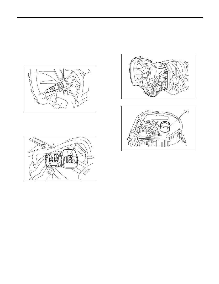
3) Remove the input shaft.
4) Lift up the lever on the rear side of transmission
harness connector, and then disconnect it from the
stay.
5) Disconnect the inhibitor switch connector from
the stay.
6) Remove the air breather hose. <Ref. to 4AT-65,
REMOVAL, Air Breather Hose.>
7) Remove the oil charge pipe. <Ref. to 4AT-66,
REMOVAL, Oil Charge Pipe.>
8) Remove the ATF inlet and outlet pipes. <Ref. to
4AT-62, REMOVAL, ATF Cooler Pipe and Hose.>
9) Remove the converter case alignment bolt, and
then separate the transmission case and converter
case by lightly tapping with a plastic hammer.
NOTE:
• Be careful not to damage the oil seal and bush-
ing in the converter case with the oil pump cover.
• Do not loosen the rubber seal.
10) Remove the seal pipe.
11) Remove the front differential assembly. <Ref.
to 4AT-95, REMOVAL, Front Differential Assem-
bly.>
12) Remove the oil seal from converter case.
(A) Transmission harness connectors
(B) Inhibitor switch connector
AT-00114
AT-01351
(B)
(A)
(A) Seal pipe
AT-04678
AT-00176