Subaru Legacy IV (2008 year). Manual - part 681
4AT-72
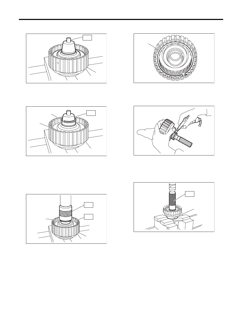
Transfer Clutch
AUTOMATIC TRANSMISSION
4) Attach the ST to the rear drive shaft.
ST
499257300
SNAP RING OUTER GUIDE
5) Install the snap ring to the ST.
ST
499257300
SNAP RING OUTER GUIDE
6) Install the snap ring to the rear drive shaft using
ST1 and ST2.
ST1
499257300
SNAP RING OUTER GUIDE
ST2
499247400
INSTALLER
7) Install the driven plate, drive plate, retaining
plate and snap ring.
8) Apply compressed air to see if the assembled
parts move smoothly.
9) Check clearance between the snap ring and
pressure plate. <Ref. to 4AT-73, INSPECTION,
Transfer Clutch.>
10) Press-fit new ball bearing using ST.
ST
899580100
INSTALLER
(A) Rear drive shaft
(A) Snap ring
(B) Rear drive shaft
(A) Snap ring
(B) Rear drive shaft
AT-00135
(A)
ST
AT-00136
(A)
(B)
ST
AT-00137
(A)
(B)
ST2
ST1
(A) Snap ring
(A) Ball bearing
AT-00138
(A)
AT-00139
AT-00140
(A)
ST