Subaru Legacy IV (2008 year). Manual - part 278


  Index      Subaru     Subaru Legacy IV - service repair manual 2008 year


Search            


Content   ..  276  277  278  279   ..


Subaru Legacy IV (2008 year). Manual - part 278


ME(H4DOTC)-92

Cylinder Block

MECHANICAL

2) Using the piston, insert the piston ring and oil
ring into the cylinder so that they are perpendicular
to the cylinder wall, and measure the piston ring
gap with a thickness gauge.

3) Fit the piston ring straight into the piston ring
groove, then measure the clearance between pis-
ton ring and piston ring groove with a thickness
gauge.

NOTE:
Before measuring the clearance, clean the piston
ring groove and piston ring.

5. CONNECTING ROD

1) Replace the connecting rod, if the large or small
end thrust surface is damaged.
2) Check for bend or twist using a connecting rod
aligner. Replace the connecting rod if the bend or
twist exceeds the limit.

Limit of bend or twist per 100 mm (3.94 in) in 
length:

0.10 mm (0.0039 in)

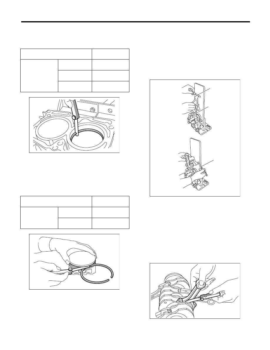
3) Install the connecting rod fitted with bearing to
the crankshaft, and measure the thrust clearance
using a thickness gauge. If the thrust clearance ex-
ceeds the standard or uneven wear is found, re-
place the connecting rod.

Connecting rod thrust clearance:

Standard

0.070 — 0.330 mm (0.0028 — 0.0130 in)

4) Inspect the connecting rod bearing for scar,
peeling, seizure, melting, wear, etc.

 Standard

mm (in)

Piston ring gap

Top ring

0.20 — 0.25

(0.0079 — 0.0098)

Second ring

0.37 — 0.52

(0.015 — 0.020)

Oil ring rail

0.20 — 0.50

(0.0079 — 0.0197)

 Standard

mm (in)

Clearance between 
piston ring and 
piston ring groove

Top ring

0.040 — 0.080

(0.0016 — 0.0031)

Second ring

0.030 — 0.070

(0.0012 — 0.0028)

ME-00177

ME-00178

(A) Thickness gauge

(B) Connecting rod

( A )

( A )

( B )

( B )

ME-00179

ME-00180

ME(H4DOTC)-93

Cylinder Block

MECHANICAL

5) Measure the oil clearance on each connecting
rod bearing using plastigauge. If any oil clearance
is not within the standard, replace the defective
bearing with a new part of standard size or under-
size as necessary.

Connecting rod oil clearance:

Standard

0.017 — 0.045 mm (0.0007 — 0.0018 in)

6) Inspect the bushing at connecting rod small end,
and replace with a new part if worn or damaged.
7) Measure the piston pin clearance at connecting
rod small end. If the measured value is not within
the standard, replace it with a new part.

Clearance between piston pin and bushing:

Standard

0 — 0.022 mm (0 — 0.0009 in)

8) The replacement procedure for the connecting
rod small end bushing is as follows.

(1) Remove the bushing from connecting rod
with ST and press.
(2) Press the bushing with the ST after applying
oil on the periphery of new bushing.

ST

499037100

CONNECTING ROD 
BUSHING REMOVER AND 
INSTALLER

(3) Make two 3 mm (0.12 in) holes in the
pressed bushing by aligning with the pre-manu-
factured holes on the connecting rod, and ream
the inside of the bushing.
(4) After completion of reaming, clean the bush-
ing to remove chips.

6. CRANKSHAFT AND CRANKSHAFT 
BEARING

1) Clean the crankshaft completely, and check it for
cracks using liquid penetrant tester. If defective, re-
place the crankshaft.
2) Measure warping of the crankshaft. If it exceeds
the limit, correct or replace it.

NOTE:
If a suitable V-block is not available, using just the
#1 and #5 crankshaft bearings on cylinder block,
position the crankshaft on cylinder block. Then,
measure the crankshaft bend using a dial gauge.

Crankshaft bend limit:

0.035 mm (0.0014 in)

Unit: mm (in)

Bearing

Bearing size

(Thickness at center)

Outer diameter of 

crank pin

Standard

1.490 — 1.502

(0.0587 — 0.0591)

51.984 — 52.000

(2.0466 — 2.0472)

0.03 

(0.0012)

undersize

1.504 — 1.512

(0.0592 — 0.0595)

51.954 — 51.970

(2.0454 — 2.0461)

0.05 

(0.0020)

undersize

1.514 — 1.522

(0.0596 — 0.0599)

51.934 — 51.950

(2.0447 — 2.0453)

0.25 

(0.0098)

undersize

1.614 — 1.622

(0.0635 — 0.0639)

51.734 — 51.750

(2.0368 — 2.0374)

ME-00181

ME-00174

ME-00182

ST

ME-00183

ME(H4DOTC)-94

Cylinder Block

MECHANICAL

3) Inspect the crank journal and crank pin for wear.
If they are not within the standard, replace the bear-
ing with a suitable (undersize) one, and replace or
grind to correct the crankshaft as necessary. When
grinding the crank journal or crank pin, finish them
to the specified dimensions according to the under-
size bearing to be used.

Crank pin:

Out-of-roundness

0.003 mm (0.0001 in)

Cylindricality

0.004 mm (0.0002 in)

Grinding limit (dia.)

To 51.750 mm (2.0374 in)

Crank journal:

Out-of-roundness

0.005 mm (0.0002 in)

Cylindricality

0.006 mm (0.0002 in)

Grinding limit (dia.)

To 59.758 mm (2.3527 in)

ME-00184

Unit: mm (in)


Crank journal diameter

Crank pin outer diameter

#1, #3

#2, #4, #5

Standard

Journal O.D.

59.992 — 60.008

(2.3619 — 2.3625)

59.992 — 60.008

(2.3619 — 2.3625)

51.984 — 52.000

(2.0466 — 2.0472)

Bearing size
(Thickness at center)

1.998 — 2.011

(0.0787 — 0.0792)

2.000 — 2.013

(0.0787 — 0.0793)

1.490 — 1.502

(0.0587 — 0.0591)

0.03 (0.0012)
Undersize

Journal O.D.

59.962 — 59.978

(2.3607 — 2.3613)

59.962 — 59.978

(2.3607 — 2.3613)

51.954 — 51.970

(2.0454 — 2.0461)

Bearing size
(Thickness at center)

2.017 — 2.020

(0.0794 — 0.0795)

2.019 — 2.022

(0.0795 — 0.0796)

1.504 — 1.512

(0.0592 — 0.0595)

0.05 (0.0020)
Undersize

Journal O.D.

59.942 — 59.958

(2.3599 — 2.3605)

59.942 — 59.958

(2.3599 — 2.3605)

51.934 — 51.950

(2.0447 — 2.0453)

Bearing size
(Thickness at center)

2.027 — 2.030

(0.0798 — 0.0799)

2.029 — 2.032

(0.0799 — 0.0800)

1.514 — 1.522

(0.0596 — 0.0599)

0.25 (0.0098)
Undersize

Journal O.D.

59.742 — 59.758

(2.3520 — 2.3527)

59.742 — 59.758

(2.3520 — 2.3527)

51.734 — 51.750

(2.0368 — 2.0374)

Bearing size
(Thickness at center)

2.127 — 2.130

(0.0837 — 0.0839)

2.129 — 2.132

(0.0838 — 0.0839)

1.614 — 1.622

(0.0635 — 0.0639)

ME(H4DOTC)-95

Cylinder Block

MECHANICAL

4) Use a thickness gauge to measure the thrust
clearance of crankshaft at #5 crank journal bearing.
If clearance exceeds the standard, replace the
bearing.

Crankshaft thrust clearance:

Standard

0.030 — 0.115 mm (0.0012 — 0.0045 in)

5) Inspect individual crankshaft bearings for signs
of flaking, seizure, melting and wear.
6) Measure the oil clearance on each crankshaft
bearing using plastigauge. If the measured value is
out of standard, replace the defective bearing with
an undersize one, and replace or grind to correct
the crankshaft as necessary.

Crankshaft oil clearance:

Standard

0.010 — 0.030 mm (0.0004 — 0.0012 in)

ME-00322


Content   ..  276  277  278  279   ..