Subaru Legacy IV (2008 year). Manual - part 276


  Index      Subaru     Subaru Legacy IV - service repair manual 2008 year


Search            


Content   ..  274  275  276  277   ..


Subaru Legacy IV (2008 year). Manual - part 276


ME(H4DOTC)-84

Cylinder Block

MECHANICAL

(7) Set the parts so that the #3 and #4 cylinders
are on the upper side. Following the same pro-
cedures as used for #1 and #2 cylinders, install
the pistons and piston pins.
(8) Install the service hole cover.

NOTE:
Use new O-rings.

Tightening torque:

6.4 N·m (0.7 kgf-m, 4.7 ft-lb)

22) Install the water pipe assembly.

NOTE:
Use new O-rings.

Tightening torque:

6.4 N·m (0.7 kgf-m, 4.7 ft-lb)

23) Install the water tank pipe assembly.

Tightening torque:

6.4 N·m (0.7 kgf-m, 4.7 ft-lb)

24) Install the baffle plate.

Tightening torque:

6.4 N·m (0.7 kgf-m, 4.7 ft-lb)

25) Install the oil strainer.

NOTE:
Use new O-rings.

Tightening torque:

10 N·m (1.0 kgf-m, 7.2 ft-lb)

26) Tighten the oil strainer stay together with the
baffle plate.

Tightening torque:

6.4 N·m (0.7 kgf-m, 4.7 ft-lb)

27) Apply liquid gasket to the mating surfaces of oil
pan, and install the oil pan.

NOTE:
Install within 5 minutes after applying liquid gasket.

Liquid gasket:

THREE BOND 1217G (Part No. K0877Y0100) 
or equivalent

Tightening torque:

5 N·m (0.5 kgf-m, 3.7 ft-lb)

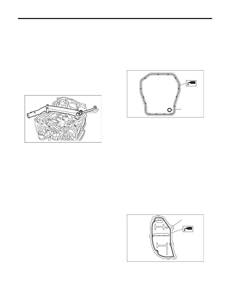
28) Apply liquid gasket to the mating surfaces of
the oil separator cover and the threaded portion of
bolt (A) shown in the figure (when reusing the bolt),
and then install the oil separator cover.

NOTE:
• Install within 5 minutes after applying liquid gas-
ket.
• Use new oil separator cover.

Liquid gasket:

Mating surface

THREE BOND 1217G (Part No. 
K0877Y0100) or equivalent

Bolt thread (A) (when reusing the bolt)

THREE BOND 1324 (Part No. 004403042) or 
equivalent

Tightening torque:

6.4 N·m (0.7 kgf-m, 4.7 ft-lb)

ME-00300

(A) Gasket

LU-02353

(A)

ME-03333

(A)

ME(H4DOTC)-85

Cylinder Block

MECHANICAL

29) Use the ST to lock the crankshaft, and install
the drive plate. (AT model)
ST

498497100

CRANKSHAFT STOPPER

Tightening torque:

72 N·m (7.3 kgf-m, 53.1 ft-lb)

30) Install the flywheel. (MT model) <Ref. to CL-16,
INSTALLATION, Flywheel.>
31) Install the clutch disc and cover. (MT model) <Ref.
to CL-13, INSTALLATION, Clutch Disc and Cover.>
32) Install the oil pump.

(1) Install the front oil seal using the ST.

ST

499587100

OIL SEAL INSTALLER

NOTE:
Use a new front oil seal.

(2) Apply liquid gasket to the matching surface
of oil pump.

NOTE:
Install within 5 minutes after applying liquid gasket.

Liquid gasket:

THREE BOND 1217G (Part No. K0877Y0100) 
or equivalent

(3) Apply a coat of engine oil to the inside of oil
seal.

(4) Install the oil pump to cylinder block. Be
careful not to damage the oil seal during instal-
lation.

NOTE:
• Make sure the oil seal lip is not folded.
• Align the flat surface of oil pump’s inner rotor with
crankshaft before installation.
• Use new O-rings and oil seals.
• Do not forget to assemble O-rings.

(5) Apply liquid gasket to the three bolts thread
shown in figure. (when reusing bolts)

Liquid gasket:

THREE BOND 1324 (Part No. 004403042) or 
equivalent

Tightening torque:

6.4 N·m (0.7 kgf-m, 4.7 ft-lb)

(A) O-ring

ME-00136

ST

LU-00021

ST

ME-00165

(A)

ME-00312

LU-02103

T

ME(H4DOTC)-86

Cylinder Block

MECHANICAL

33) Install the water pump and gasket.

NOTE:
• When installing the water pump, tighten bolts in
two stages in alphabetical sequence as shown in
the figure.
• Use a new gasket.

Tightening torque:

First: 12 N·m (1.2 kgf-m, 8.9 ft-lb)
Second: 12 N·m (1.2 kgf-m, 8.9 ft-lb)

34) Install the water by-pass pipe for heater.

Tightening torque:

6.4 N·m (0.7 kgf-m, 4.7 ft-lb)

35) Install the oil cooler. <Ref. to LU(H4SO)-22, IN-
STALLATION, Engine Oil Cooler.>
36) Install the oil filter. <Ref. to LU(H4SO)-23, IN-
STALLATION, Engine Oil Filter.>
37) Install the cylinder head. <Ref. to
ME(H4DOTC)-65, INSTALLATION, Cylinder
Head.>
38) Install the camshaft. <Ref. to ME(H4DOTC)-
59, INSTALLATION, Camshaft.>
39) Install the generator and A/C compressor with
their brackets.

Tightening torque:

36 N·m (3.7 kgf-m, 26.6 ft-lb)

40) Install the crank sprocket. <Ref. to
ME(H4DOTC)-57, INSTALLATION, Crank Sprock-
et.>
41) Install the cam sprocket. <Ref. to
ME(H4DOTC)-56, INSTALLATION, Cam Sprock-
et.>
42) Install the timing belt. <Ref. to ME(H4DOTC)-
49, INSTALLATION, Timing Belt.>
43) Adjust the valve clearance. <Ref. to
ME(H4DOTC)-28, ADJUSTMENT, Valve Clear-
ance.>

44) Install the rocker cover.

(1) Install the rocker cover gasket to the rocker
cover. (Outer periphery and ignition coil section)

NOTE:
Use a new rocker cover gasket.

(2) Apply liquid gasket to the specified point of
the cylinder head.

NOTE:
Install within 5 minutes after applying liquid gasket.

Liquid gasket:

THREE BOND 1217G (Part No. K0877Y0100) 
or equivalent

(3) Install the rocker cover on cylinder head.
Ensure the gasket is properly positioned during
installation.
(4) Temporarily tighten the rocker cover tight-
ening bolts in alphabetical order shown in the
figure, and then tighten to specified torque in al-
phabetical order.

Tightening torque:

6.4 N·m (0.7 kgf-m, 4.7 ft-lb)

ME-02463

(F)

(E)

(D)

(C)

(B)

(A)

ME-03143

ME-00777

(E)

(F)

(H)

(G)

(D),(L)

(A),(I)

(C),(K)

(B),(J)

ME(H4DOTC)-87

Cylinder Block

MECHANICAL

45) Install the timing belt cover. <Ref. to
ME(H4DOTC)-46, INSTALLATION, Timing Belt
Cover.>
46) Install the crank pulley. <Ref. to ME(H4DOTC)-
44, INSTALLATION, Crank Pulley.>
47) Install the intake manifold. <Ref. to
FU(H4DOTC)-20, INSTALLATION, Intake Mani-
fold.>
48) Install the V-belts. <Ref. to ME(H4DOTC)-42,
INSTALLATION, V-belt.>

C: DISASSEMBLY

1) Remove the connecting rod cap.
2) Remove the connecting rod bearing.

NOTE:
Keep the removed connecting rods, connecting rod
caps and bearings in order so that they are kept in
their original combinations/groups, and not mixed
together.
3) Remove the piston rings using piston ring ex-
pander.
4) Remove the oil ring by hand.

NOTE:
Arrange the removed piston rings in proper order,
to prevent confusion.
5) Remove the snap ring.

(1)

Connecting rod cap

(4)

Second ring

(6)

Snap ring

(2)

Connecting rod bearing

(5)

Oil ring

(7)

Connecting rod

(3)

Top 

ring


ME-03556

(2)

(2)

(6)

(5)

(4)

(3)

(1)

(7)


Content   ..  274  275  276  277   ..