Subaru Legacy IV (2008 year). Manual - part 277
ME(H4DOTC)-88
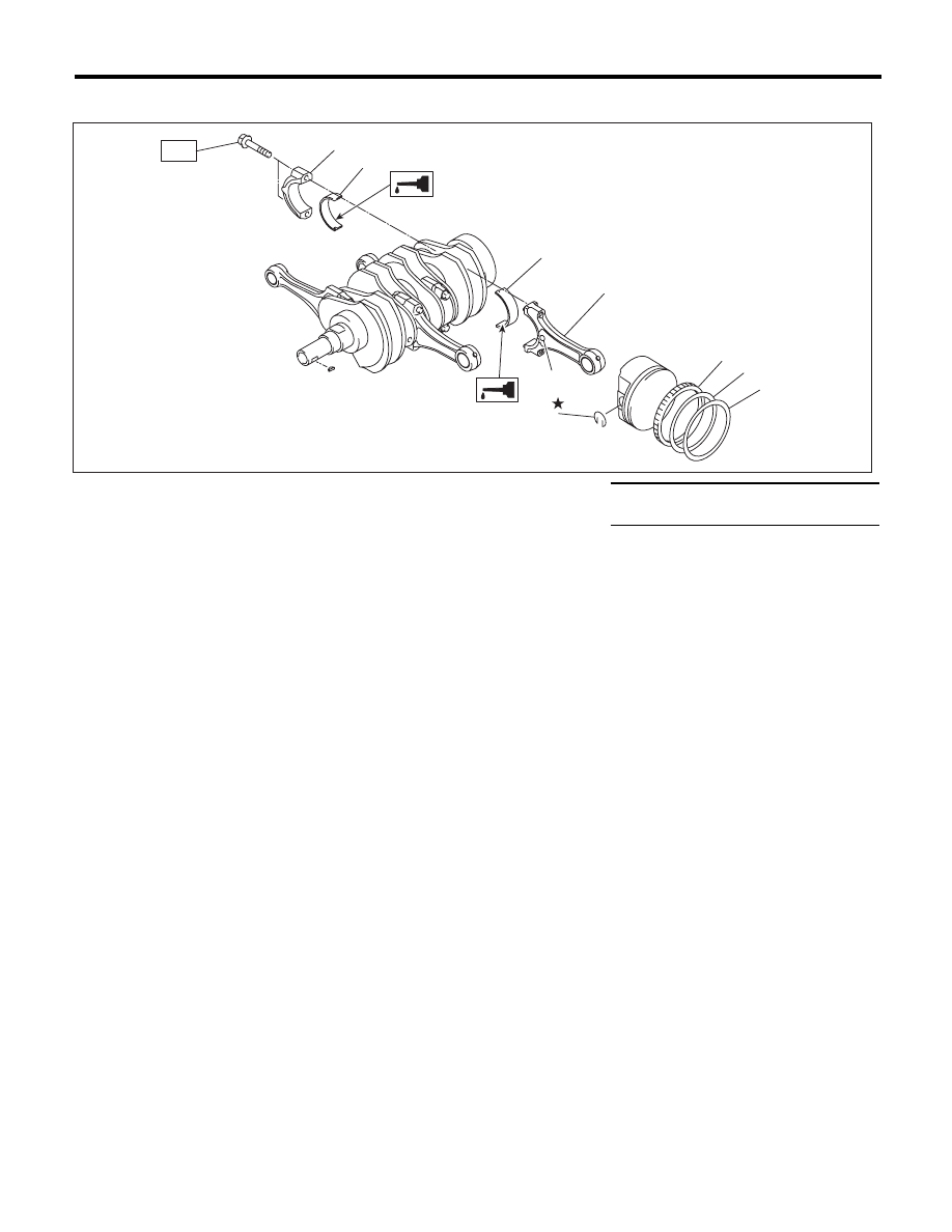
Cylinder Block
MECHANICAL
D: ASSEMBLY
1) Apply oil to the surface of the connecting rod
bearings, and install the connecting rod bearings
on connecting rods and connecting rod caps.
2) Position each connecting rod with a side mark
facing forward, and install it.
3) Attach the connecting rod cap, and tighten with
the connecting rod bolt. Make sure the arrow mark
on connecting rod cap facing front during installa-
tion.
NOTE:
• Each connecting rod has its own mating cap.
Make sure that they are assembled correctly by
checking their matching number.
• When tightening the connecting rod nuts, apply
oil on the threads.
Tightening torque:
52 N·m (5.3 kgf-m, 38.4 ft-lb)
4) Install the oil ring upper rail, expander and lower
rail by hand.
5) Install the second ring and top ring using piston
ring expander.
NOTE:
Assemble so that the piston ring mark “R” faces the
top side of the piston.
(1)
Connecting rod bearing
(5)
Second ring
Tightening torque:N·m (kgf-m, ft-lb)
(2)
Connecting rod
(6)
Top ring
T: 52 (5.3, 38.4)
(3)
Connecting rod cap
(7)
Snap ring
(4)
Oil ring
(8)
Side mark
ME-02985
(1)
(1)
(7)
(4)
(5)
(6)
(3)
T
(2)
(8)