Subaru Legacy IV (2008 year). Manual - part 270


  Index      Subaru     Subaru Legacy IV - service repair manual 2008 year


Search            


Content   ..  268  269  270  271   ..


Subaru Legacy IV (2008 year). Manual - part 270


ME(H4DOTC)-60

Camshaft

MECHANICAL

2) Install the camshaft cap.

(1) Apply small amount of liquid gasket to the
mating surface of cap.

NOTE:
• Install within 5 minutes after applying liquid gas-
ket.
• Do not apply liquid gasket excessively. Applying
excessively may cause excess gasket to come out
and flow toward oil seal, resulting in oil leak.

Liquid gasket:

THREE BOND 1217G (Part No. K0877Y0100) 
or equivalent

(2) Apply a thin coat of engine oil to the cap
journal surface, and install the camshaft cap to
the camshaft.
(3) Gradually tighten the camshaft cap in at
least two stages in alphabetical order shown in
the figure, and then tighten to specified torque.

Tightening torque:

T1: 9.75 N·m (1.0 kgf-m, 7.2 ft-lb)
T2: 20 N·m (2.0 kgf-m, 14.8 ft-lb)

(4) After tightening the camshaft cap, ensure
the camshaft rotates only slightly while holding
it at base circle.

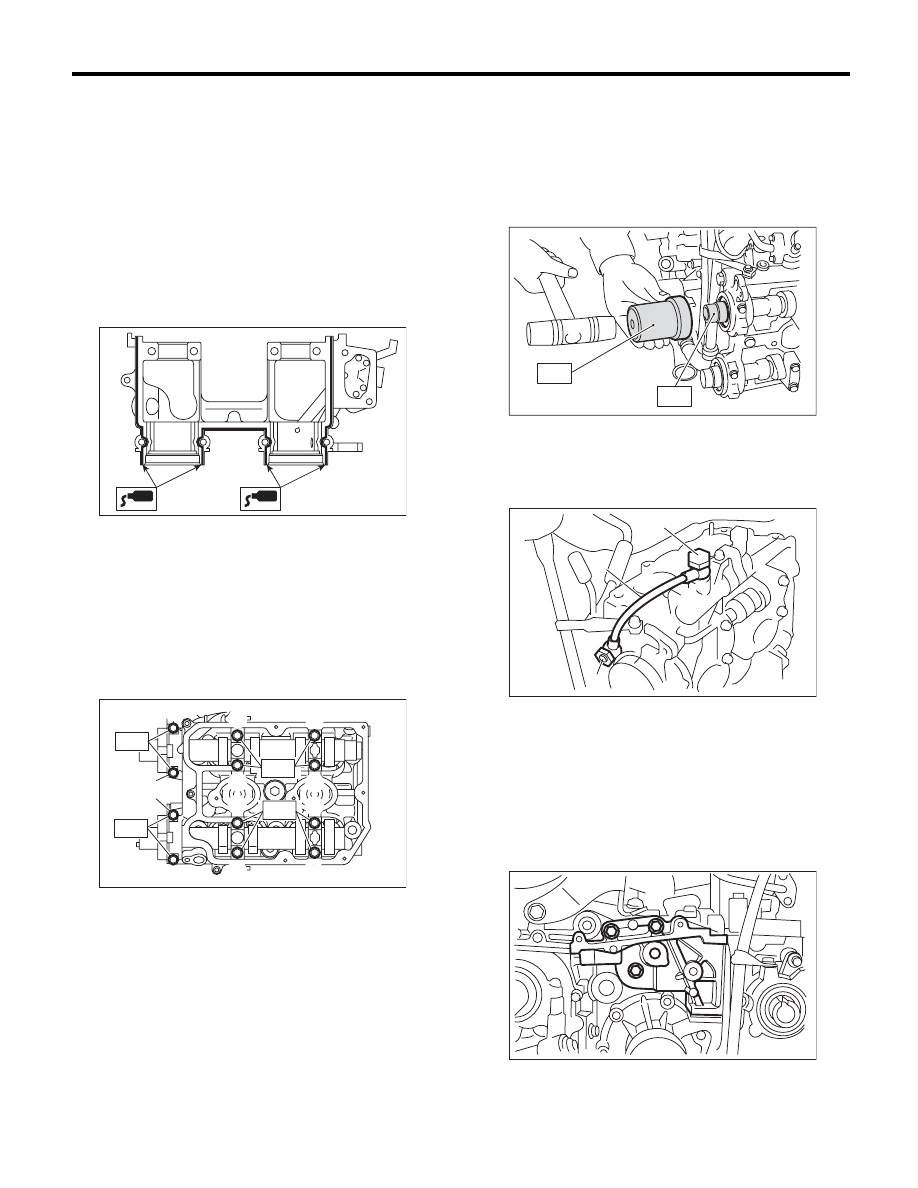
3) Apply a coat of engine oil to the camshaft oil seal
periphery and oil seal lips, then install the oil seal
on the camshaft using ST1 and ST2.

NOTE:
Use a new oil seal.
ST1

499587600

OIL SEAL INSTALLER

ST2

499597200

OIL SEAL GUIDE

4) Install the oil pipe to the front camshaft cap using
the union screw without filter (without protrusion).

Tightening torque:

29 N·m (3.0 kgf-m, 21.4 ft-lb)

5) Similarly, install the parts on right-hand side.
6) Install the tensioner bracket.

Tightening torque:

24.5 N·m (2.5 kgf-m, 18.1 ft-lb)

ME-00773

ME-02379

(G)

(C)

(A)

(K)

(L)

T1

(F)

(E)

T2

T2

(B)

(J)

(H)

(D)

 (I)

T1

(A) Union screw with filter (with protrusion)

(B) Union screw without filter (without protrusion)

(C) Oil pipe

ME-00116

ST1

ST2

(A)

(B)

ME-03555

(C)

ME-00105

ME(H4DOTC)-61

Camshaft

MECHANICAL

7) Install the timing belt cover No. 2 RH.

Tightening torque:

5 N·m (0.5 kgf-m, 3.7 ft-lb)

8) Install the timing belt cover No. 2 LH.

Tightening torque:

5 N·m (0.5 kgf-m, 3.7 ft-lb)

9) Install the cam sprocket. <Ref. to ME(H4DOTC)-
56, INSTALLATION, Cam Sprocket.>
10) Install the timing belt. <Ref. to ME(H4DOTC)-
49, INSTALLATION, Timing Belt.>
11) Adjust the valve clearance. <Ref. to
ME(H4DOTC)-28, ADJUSTMENT, Valve Clear-
ance.>

12) Install the rocker cover.

(1) Install the rocker cover gasket to the rocker
cover. (Outer periphery and ignition coil section)

NOTE:
Use a new rocker cover gasket.

(2) Apply liquid gasket to the specified point of
the cylinder head.

NOTE:
Install within 5 minutes after applying liquid gasket.

Liquid gasket:

THREE BOND 1217G (Part No. K0877Y0100) 
or equivalent

(3) Install the rocker cover on cylinder head.
Ensure the gasket is properly positioned during
installation.
(4) Temporarily tighten the rocker cover tight-
ening bolts in alphabetical order shown in the
figure, and then tighten to specified torque in al-
phabetical order.

Tightening torque:

6.4 N·m (0.7 kgf-m, 4.7 ft-lb)

ME-00107

ME-00106

ME-03143

ME-00777

(E)

(F)

(H)

(G)

(D),(L)

(A),(I)

(C),(K)

(B),(J)

ME(H4DOTC)-62

Camshaft

MECHANICAL

13) Connect the PCV hose to the rocker cover.

NOTE:
Use a new clamp for the PCV hose clamp, fit the
cut out in the ST with the protrusion on the clamp as
shown in the figure, and lock the clamp.
ST

18353AA000

CLAMP PLIERS

14) Connect the connector to the oil flow control so-
lenoid valve.

15) Tighten the ignition coil. <Ref. to IG(H4DOTC)-
7, INSTALLATION, Ignition Coil.>
16) Install the timing belt cover. <Ref. to
ME(H4DOTC)-46, INSTALLATION, Timing Belt
Cover.>
17) Install the crank pulley. <Ref. to ME(H4DOTC)-
44, INSTALLATION, Crank Pulley.>
18) Install the V-belts. <Ref. to ME(H4DOTC)-42,
INSTALLATION, V-belt.>

C: INSPECTION

1) Measure the bend, and repair or replace if nec-
essary.

Service limit:

0.020 mm (0.00079 in) or less

2) Check the journal for damage and wear. Re-
place if faulty.
3) Check the cutout portion used for camshaft sen-
sor for damage. Replace if faulty.
4) Measure the outside diameter of camshaft jour-
nal. If the journal diameter is not within the stan-
dard, check the oil clearance.

5) Measure the camshaft journal oil clearance.

(1) Clean the camshaft cap and cylinder head
camshaft journal.
(2) Place the camshaft on the cylinder head.
(Without installing the valve lifter.)
(3) Place a plastigauge across each camshaft
journals.
(4) Gradually tighten the camshaft cap in at
least two stages in alphabetical order shown in
the figure, and then tighten to specified torque.
Do not turn the camshaft.

Tightening torque:

T1: 9.75 N·m (1.0 kgf-m, 7.2 ft-lb)
T2: 20 N·m (2.0 kgf-m, 14.8 ft-lb)

ME-03630

ME-03094

 Camshaft 

journal

Front

Center, rear

Standard

mm (in)

37.946 — 37.963 

(1.4939 — 1.4946)

29.946 — 29.963 

(1.1790 — 1.1796)

ME-00118

ME-02379

(G)

(C)

(A)

(K)

(L)

T1

(F)

(E)

T2

T2

(B)

(J)

(H)

(D)

 (I)

T1

ME(H4DOTC)-63

Camshaft

MECHANICAL

(5) Remove the camshaft cap.
(6) Measure the widest point of the plastigauge
on each journal. If oil clearance exceeds the
standard, replace the camshaft. If necessary,
replace the camshaft caps and cylinder head as
a set.

Standard:

0.037 — 0.072 mm (0.0015 — 0.0028 in)

(7) Completely remove the plastigauge.

6) Check the cam face condition; remove the minor
faults by grinding with oil stone. Measure the cam
height H. If it exceeds the standard or offset wear
occurs, replace it.

Cam height H:

Standard

Intake

46.55 — 46.65 mm (1.833 — 1.837 in)

Exhaust

46.75 — 46.85 mm (1.841 — 1.844 in)

Cam base circle diameter A:

37.0 mm (1.457 in)

7) Measure the thrust clearance of camshaft with
setting the dial gauge at end of camshaft. If the
thrust clearance exceeds the standard or there is
offset wear, replace the camshaft caps and cylinder
head as a set. If necessary replace the camshaft.

Standard:

0.068 — 0.116 mm (0.0027 — 0.0047 in)

ME-00119

ME-00276

H

A

ME-00121


Content   ..  268  269  270  271   ..