Subaru Legacy IV (2008 year). Manual - part 268


  Index      Subaru     Subaru Legacy IV - service repair manual 2008 year


Search            


Content   ..  266  267  268  269   ..


Subaru Legacy IV (2008 year). Manual - part 268


ME(H4DOTC)-52

Timing Belt

MECHANICAL

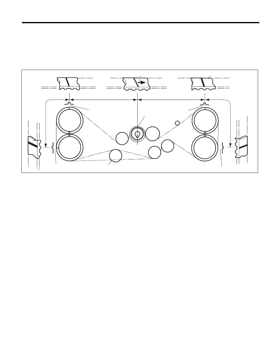
8) Install the timing belt.
Align the alignment mark on the timing belt with marks on the sprockets in the alphabetical order shown in
the figure. While aligning marks, position the timing belt properly.

CAUTION:
• Disengagement of more than three timing belt teeth may result in interference between the valve
and piston.
• Make sure that the direction of belt rotation is correct.

(1)

Arrow mark

(4)

54.5-teeth length

(6)

28-teeth length

(2)

Timing belt

(5)

51-teeth length

(7)

Install it in the end

(3)

28-teeth length


ME-03137

(1)

(2)

(5)

(6)

(4)

(D)

(A)

(C)

(B)

(E)

(3)

RH-IN

RH-EX

LH-EX

LH-IN

(7)

ME(H4DOTC)-53

Timing Belt

MECHANICAL

9) Install the belt idlers.

Tightening torque:

39 N·m (4.0 kgf-m, 28.8 ft-lb)

NOTE:
Make sure that the marks on the timing belt and
sprockets are aligned.

10) After ensuring that the marks on the timing belt
and sprockets are aligned, remove the stopper pin
from tensioner adjuster.

11) Install the timing belt guide. (MT model)

(1) Temporarily tighten the bolts mounting the
timing belt guide.

NOTE:
• Before installing bolts, clean the bolt holes of tim-
ing belt cover.
• Apply liquid gasket to the threaded portion of
cam sprocket. (when reusing bolts)

Liquid gasket:

THREE BOND 1324 (Part No. 004403042) or 
equivalent

(2) Check and adjust the clearance between
timing belt and timing belt guide using a thick-
ness gauge.

Clearance:

1.0

r

0.5 mm (0.039

r

0.020 in)

ME-00090

ME-00245

ME-00230

ME-00246

ME-03138

ME-00731

ME-00732

ME(H4DOTC)-54

Timing Belt

MECHANICAL

(3) Tighten the bolts mounting the timing belt
guide.

Tightening torque:

9.75 N·m (1.0 kgf-m, 7.2 ft-lb)

Tightening torque:

6.4 N·m (0.7 kgf-m, 4.7 ft-lb)

Tightening torque:

6.4 N·m (0.7 kgf-m, 4.7 ft-lb)

Tightening torque:

6.4 N·m (0.7 kgf-m, 4.7 ft-lb)

12) Install the timing belt cover. <Ref. to
ME(H4DOTC)-46, INSTALLATION, Timing Belt
Cover.>
13) Install the crank pulley. <Ref. to ME(H4DOTC)-
44, INSTALLATION, Crank Pulley.>
14) Install the V-belts. <Ref. to ME(H4DOTC)-42,
INSTALLATION, V-belt.>

C: INSPECTION

1. TIMING BELT

1) Check the timing belt teeth for breaks, cracks or
wear. If any fault is found, replace the timing belt.
2) Check the condition on the back surface of the
timing belt. If cracks are found, replace the timing
belt.

CAUTION:
• Be careful not to let oil, grease or coolant
contact the timing belt. Remove quickly and
thoroughly if this happens.
• Do not bend the timing belt sharply.

In radial diameter h:

60 mm (2.36 in) or more

ME-00247

ME-03124

ME-00728

ME-00729

ME-00248

h

ME(H4DOTC)-55

Timing Belt

MECHANICAL

2. AUTOMATIC BELT TENSION ADJUSTER

1) Visually check the oil seals for leaks, and rod
ends for abnormal wear and scratches. If neces-
sary, replace the automatic belt tension adjuster
assembly.

NOTE:
Slight traces of oil on the oil seal of the rod does not
indicate a problem.
2) Check that the adjuster rod does not move when
a pressure of 165 N (16.8 kgf, 37.1 lbf) is applied to
it. This is to check adjuster rod stiffness.
3) If the adjuster rod is not stiff and moves freely
when applying 165 N (16.8 kgf, 37.1 lbf), check it
using the following procedures:

(1) Slowly press the adjuster rod down to the
end surface of cylinder. Repeat this operation
two to three times.
(2) With the adjuster rod moved all the way up,
apply a pressure of 165 N (16.8 kgf, 37.1 lbf) to
it, and check the adjuster rod stiffness.
(3) If the adjuster rod is not stiff and moves
down, replace the automatic belt tension adjust-
er assembly with a new part.

CAUTION:
• Always use a vertical type pressing tool to
move the adjuster rod down.
• Do not use a lateral type vise.
• Push the adjuster rod vertically.
• Press-in the push adjuster rod gradually tak-
ing three minutes or more.
• Do not allow press pressure to exceed 9,807
N (1,000 kgf, 2,205 lbf).
• Push in the adjuster rod to the end face of the
cylinder. However, do not press the adjuster
rod below the end face of the cylinder. Doing so
may damage the cylinder.
4) Measure the amount of rod protrusion “H” from
the end surface of the body. If it is not within spec-
ifications, replace the automatic belt tension adjust-
er assembly with a new part.

Amount of rod protrusion H:

5.2 — 6.2 mm (0.205 — 0.244 in)

3. BELT TENSION PULLEY

1) Check the mating surfaces of timing belt and
contact point of adjuster rod for abnormal wear or
scratches. Replace the automatic belt tension ad-
juster assembly with a new part if faulty.
2) Check the belt tension pulley for smooth rota-
tion. Replace the automatic belt tension adjuster
assembly with a new part if abnormal noise or ex-
cessive play occurs.
3) Check the belt tension pulley for grease leakage.

4. BELT IDLER

1) Check the belt idler for smooth rotation. Replace
if noise or excessive play occurs.
2) Check the outer contacting surfaces of idler pul-
ley for abnormal wear and scratches.
3) Check the belt idler for grease leakage.

ME-00249

H


Content   ..  266  267  268  269   ..