Subaru Legacy IV (2008 year). Manual - part 271


  Index      Subaru     Subaru Legacy IV - service repair manual 2008 year


Search            


Content   ..  269  270  271  272   ..


Subaru Legacy IV (2008 year). Manual - part 271


ME(H4DOTC)-64

Cylinder Head

MECHANICAL

19.Cylinder Head

A: REMOVAL

NOTE:
• When replacing the single part, perform the work
with the engine installed to body. Refer to “Valve
Clearance” for preparation procedures. <Ref. to
ME(H4DOTC)-26, INSPECTION, Valve Clear-
ance.>
• When performing the work with the engine in-
stalled to body, the following parts must also be re-
moved/installed.

• Center exhaust pipe <Ref. to EX(H4DOTC)-7,
REMOVAL, Center Exhaust Pipe.> <Ref. to
EX(H4DOTC)-9, INSTALLATION, Center Ex-
haust Pipe.>
• Turbocharger <Ref. to IN(H4DOTC)-14, RE-
MOVAL, Turbocharger.> <Ref. to IN(H4DOTC)-
15, INSTALLATION, Turbocharger.>
• Joint pipe <Ref. to EX(H4DOTC)-11, REMOV-
AL, Joint Pipe.> <Ref. to EX(H4DOTC)-11, IN-
STALLATION, Joint Pipe.>
• Front exhaust pipe <Ref. to EX(H4DOTC)-5,
REMOVAL, Front Exhaust Pipe.> <Ref. to
EX(H4DOTC)-6, INSTALLATION, Front Exhaust
Pipe.>

1) Remove the V-belts. <Ref. to ME(H4DOTC)-41,
REMOVAL, V-belt.>
2) Remove the intake manifold. <Ref. to
FU(H4DOTC)-16, REMOVAL, Intake Manifold.>
3) Remove the crank pulley. <Ref. to
ME(H4DOTC)-44, REMOVAL, Crank Pulley.>
4) Remove the timing belt cover. <Ref. to
ME(H4DOTC)-46, REMOVAL, Timing Belt Cover.>
5) Remove the timing belt. <Ref. to ME(H4DOTC)-
47, REMOVAL, Timing Belt.>
6) Remove the cam sprocket. <Ref. to
ME(H4DOTC)-56, REMOVAL, Cam Sprocket.>
7) Remove the bolt which installs the A/C compres-
sor bracket on cylinder head.
8) Remove the secondary air combination valve.
<Ref. to EC(H4DOTC)-22, REMOVAL, Secondary
Air Combination Valve.>

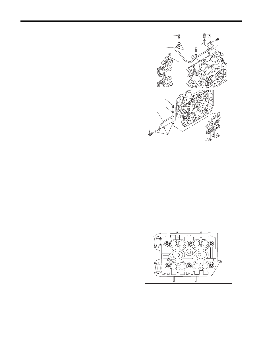
9) Remove the oil pipe.

10) Remove the camshaft. <Ref. to ME(H4DOTC)-
58, REMOVAL, Camshaft.>
11) Remove the oil level gauge guide. (LH side
only)
12) Remove the cylinder head bolts in alphabetical
order shown in the figure.

NOTE:
Leave the bolts (A) and (D) engaged by three or
four threads to prevent the cylinder head from fall-
ing.

(A) Union screw with filter (with protrusion)

(B) Union screw without filter (without protrusion)

(C) Oil pipe

(D) Gasket

ME-03919

(A)

(B)

(C)

(D)

(D)

(A)

(B)

(C)

(D)

(D)

(D)

ME-00122

(B)

(C)

(D)

(E)

(F)

(A)

ME(H4DOTC)-65

Cylinder Head

MECHANICAL

13) While tapping the cylinder head with a plastic
hammer, separate it from cylinder block. Remove
the bolts (A) and (D) to remove cylinder head.

14) Remove the cylinder head gasket.

CAUTION:
Be careful not to scratch the mating surface of
cylinder head and cylinder block.
15) Similarly, remove the right side cylinder head.

B: INSTALLATION

1) Install the cylinder head and gaskets on cylinder
block.

CAUTION:
Be careful not to scratch the mating surface of
cylinder head and cylinder block.

NOTE:
Use a new cylinder head gasket.
2) Tighten the cylinder head bolts.

(1) Apply a thin coat of engine oil to washer and
bolt thread.
(2) Tighten all bolts to 29 N·m (3.0 kgf-m, 21.4
ft-lb) in alphabetical order.
(3) Further tighten all bolts to 69 N·m (7.0 kgf-
m, 50.9 ft-lb) in alphabetical order.
(4) Loosen all the bolts by 180° in the reverse
order of installing, and loosen them further by
180°.
(5) Tighten all bolts to 49 N·m (5.0 kgf-m, 36.1
ft-lb) in alphabetical order.
(6) Tighten all bolts by 80 to 90° in alphabetical
order.
(7) Tighten all bolts again by 40 to 45° in alpha-
betical order.

CAUTION:
The tightening angle of the bolt should not ex-
ceed 45°.

(8) Further tighten the bolts (A) and (B) by 40 —
45°.

CAUTION:
Make sure the total “re-tightening angle” of the
step (7) and (8) does not exceed 90°.

3) Install the oil level gauge guide. (LH side only)

Tightening torque:

6.4 N·m (0.7 kgf-m, 4.7 ft-lb)

4) Install the camshaft. <Ref. to ME(H4DOTC)-59,
INSTALLATION, Camshaft.>

ME-00122

(B)

(C)

(D)

(E)

(F)

(A)

ME-00123

(B)

(C)

(D)

(E)

(F)

(A)

ME(H4DOTC)-66

Cylinder Head

MECHANICAL

5) Install the oil pipe.

NOTE:
Make sure not to mix up the union screws with filter
and without filter as their installation positions are
different.

Tightening torque:

T1: 8 N·m (0.8 kgf-m, 5.9 ft-lb)
T2: 29 N·m (3.0 kgf-m, 21.4 ft-lb)

6) Install the secondary air combination valve.
<Ref. to EC(H4DOTC)-23, INSTALLATION, Sec-
ondary Air Combination Valve.>
7) Install the A/C compressor bracket on cylinder
head.

Tightening torque:

36 N·m (3.7 kgf-m, 26.6 ft-lb)

8) Install the cam sprocket. <Ref. to ME(H4DOTC)-
56, INSTALLATION, Cam Sprocket.>
9) Install the timing belt. <Ref. to ME(H4DOTC)-49,
INSTALLATION, Timing Belt.>
10) Adjust the valve clearance. <Ref. to
ME(H4DOTC)-28, ADJUSTMENT, Valve Clear-
ance.>

11) Install the rocker cover.

(1) Install the rocker cover gasket to the rocker
cover. (Outer periphery and ignition coil sec-
tion)

NOTE:
Use a new rocker cover gasket.

(2) Apply liquid gasket to the specified point of
the cylinder head.

NOTE:
Install within 5 minutes after applying liquid gasket.

Liquid gasket:

THREE BOND 1217G (Part No. K0877Y0100) 
or equivalent

(3) Install the rocker cover on cylinder head.
Ensure the gasket is properly positioned during
installation.

(A) Union screw with filter (with protrusion)

(B) Union screw without filter (without protrusion)

(C) Oil pipe

(D) Gasket

ME-03920

(A)

(B)

(C)

(D)

(D)

T2

T1

T1

T2

T2

T2

(A)

(B)

(C)

(D)

(D)

(D)

ME-03143

ME(H4DOTC)-67

Cylinder Head

MECHANICAL

(4) Temporarily tighten the rocker cover tight-
ening bolts in alphabetical order shown in the
figure, and then tighten to specified torque in al-
phabetical order.

Tightening torque:

6.4 N·m (0.7 kgf-m, 4.7 ft-lb)

12) Install the timing belt cover. <Ref. to
ME(H4DOTC)-46, INSTALLATION, Timing Belt
Cover.>
13) Install the crank pulley. <Ref. to ME(H4DOTC)-
44, INSTALLATION, Crank Pulley.>
14) Install the intake manifold. <Ref. to
FU(H4DOTC)-20, INSTALLATION, Intake Mani-
fold.>
15) Install the V-belts. <Ref. to ME(H4DOTC)-42,
INSTALLATION, V-belt.>

C: DISASSEMBLY

1) Remove the valve lifter.
2) Place the cylinder head on ST1.
ST1

498267600

CYLINDER HEAD TABLE

3) Using ST2, compress the valve spring and re-
move the valve spring retainer key. Remove each
valve and valve spring.
ST2

499718000

VALVE SPRING REMOVER

NOTE:
• Mark each valve to prevent confusion.
• Pay careful attention not to damage the lips of in-
take valve oil seals and exhaust valve oil seals.
• Keep all the removed parts in order for re-install-
ing in their original positions.
• For removal and installation procedures of the
valve guide, intake valve oil seal and exhaust valve
oil seal, refer to “Inspection”. <Ref. to
ME(H4DOTC)-70, VALVE GUIDE, INSPECTION,
Cylinder Head.> <Ref. to ME(H4DOTC)-73, IN-
TAKE AND EXHAUST VALVE OIL SEAL, IN-
SPECTION, Cylinder Head.>

ME-00777

(E)

(F)

(H)

(G)

(D),(L)

(A),(I)

(C),(K)

(B),(J)

ME-03142

ST1

ST2


Content   ..  269  270  271  272   ..