Subaru Legacy IV (2008 year). Manual - part 261


  Index      Subaru     Subaru Legacy IV - service repair manual 2008 year


Search            


Content   ..  259  260  261  262   ..


Subaru Legacy IV (2008 year). Manual - part 261


ME(H4DOTC)-24

Engine Oil Pressure

MECHANICAL

6. Engine Oil Pressure
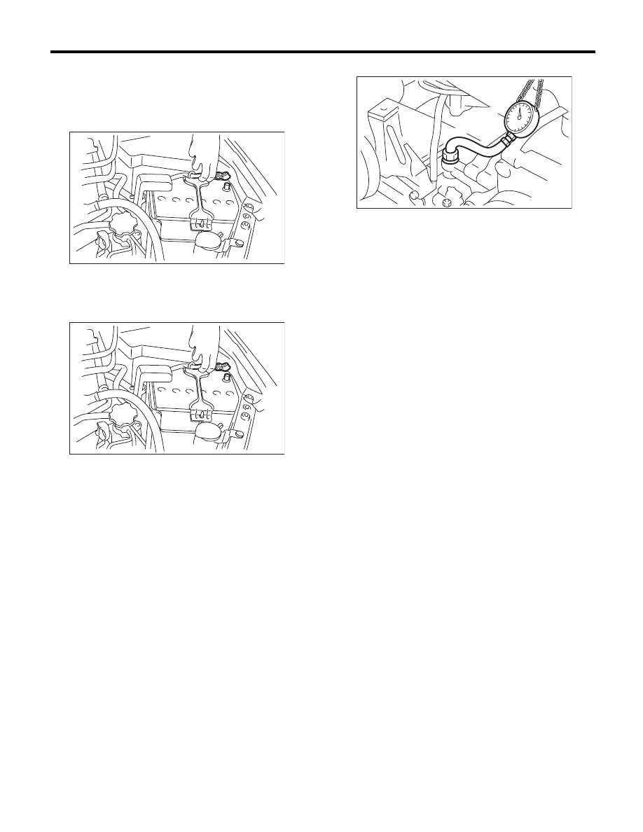
A: INSPECTION

1) Remove the collector cover.
2) Disconnect the ground cable from the battery.

3) Remove the oil pressure switch. <Ref. to
LU(H4SO)-20, REMOVAL, Oil Pressure Switch.>
4) Connect the oil pressure gauge to cylinder block.
5) Connect the ground cable to battery.

6) Start the engine, and measure the oil pressure.

Oil pressure:

Standard

98 kPa (1.0 kgf/cm

2

, 14 psi) or more 

(at 600 rpm)
294 kPa (3.0 kgf/cm

2

, 43 psi) or more 

(at 5,000 rpm)

• If the oil pressure is out of specification, check oil
pump, oil filter and lubrication line. <Ref. to
LU(H4SO)-24, INSPECTION, Engine Lubrication
System Trouble in General.>
• If the oil pressure warning light is ON and oil
pressure is within specification, check the oil pres-
sure switch. <Ref. to LU(H4SO)-24, INSPECTION,
Engine Lubrication System Trouble in General.>

NOTE:
Standard value is based on an engine oil tempera-
ture of 80°C (176°F).
7) After measuring the oil pressure, install the oil
pressure switch. <Ref. to LU(H4SO)-20, INSTAL-
LATION, Oil Pressure Switch.>

IN-00203

IN-00203

ME-03698

ME(H4DOTC)-25

Fuel Pressure

MECHANICAL

7. Fuel Pressure

A: INSPECTION

CAUTION:
• Before removing the fuel pressure gauge, re-
lease the fuel pressure.
• Be careful not to spill fuel.
• Catch the fuel from hoses using a container
or cloth.

NOTE:
If the fuel pressure is out of specification, check or
replace the pressure regulator and pressure regu-
lator vacuum hose.
1) Remove the collector cover.
2) Release the fuel pressure. <Ref. to
FU(H4DOTC)-57, RELEASING OF FUEL PRES-
SURE, PROCEDURE, Fuel.>
3) Open the fuel filler lid and remove the fuel filler
cap.
4) Disconnect the fuel delivery hose from the fuel
damper, and connect the fuel pressure gauge.

5) Start the engine.
6) Measure the fuel pressure while disconnecting
pressure regulator vacuum hose from intake mani-
fold.

NOTE:
The fuel pressure gauge registers 10 to 20 kPa (0.1
to 0.2 kgf/cm

2

, 1 to 3 psi) higher than standard val-

ues during high-altitude operations.

Fuel pressure:

Standard

284 — 314 kPa 
(2.9 — 3.2 kgf/cm

2

, 41 — 46 psi)

7) After connecting the pressure regulator vacuum
hose, measure the fuel pressure.

NOTE:
The fuel pressure gauge registers 10 to 20 kPa (0.1
to 0.2 kgf/cm

2

, 1 to 3 psi) higher than standard val-

ues during high-altitude operations.

Fuel pressure:

Standard

230 — 260 kPa 
(2.35 — 2.65 kgf/cm

2

, 33 — 38 psi)

ME-03899

ME(H4DOTC)-26

Valve Clearance

MECHANICAL

8. Valve Clearance

A: INSPECTION

NOTE:
Inspection and adjustment of valve clearance
should be performed while engine is cold.
1) Set the vehicle on a lift.
2) Remove the collector cover.
3) Disconnect the ground cable from the battery.

4) Remove the air intake duct. <Ref. to
IN(H4DOTC)-9, REMOVAL, Air Intake Duct.>
5) Remove the bolt which secures timing belt cover
RH.
6) Lift up the vehicle.
7) Remove the under cover.
8) Loosen the remaining bolts which secure timing
belt cover RH, then remove the timing belt cover.
9) Lower the vehicle.
10) When inspecting #1 and #3 cylinders

(1) Remove the air cleaner case. <Ref. to
IN(H4DOTC)-8, REMOVAL, Air Cleaner Case.>
(2) Remove the ignition coil. <Ref. to
IG(H4DOTC)-7, REMOVAL, Ignition Coil.>
(3) Place a suitable container under the vehicle.
(4) Disconnect the PCV hose from the rocker
cover RH.

NOTE:
For the PCV hose affixed with the clamp, fit the de-
pression in the ST with the protrusion of the clamp
as shown in the figure below, unlock the clamp and
disconnect.
ST

18353AA000

CLAMP PLIERS

(5) Remove the bolts, then remove the rocker
cover RH.

11) When inspecting #2 and #4 cylinders

(1) Remove the battery. <Ref. to SC(H4SO)-20,
REMOVAL, Battery.>
(2) Remove the secondary air pump. <Ref. to
EC(H4DOTC)-21, REMOVAL, Secondary Air
Pump.>
(3) Remove the ignition coil. <Ref. to
IG(H4DOTC)-7, REMOVAL, Ignition Coil.>
(4) Place a suitable container under the vehicle.
(5) Disconnect the PCV hose from the rocker
cover LH.

NOTE:
For the PCV hose affixed with the clamp, fit the de-
pression in the ST with the protrusion of the clamp
as shown in the figure below, unlock the clamp and
disconnect.
ST

18353AA000

CLAMP PLIERS

(6) Remove the bolts, then remove the rocker
cover LH.

12) Turn the crank pulley clockwise until the round
mark and arrow mark on the cam sprocket are set
to position shown in the figure.

NOTE:
Turn the crankshaft using socket wrench.

IN-00203

ME-03630

ME-03630

ME-03171

ME(H4DOTC)-27

Valve Clearance

MECHANICAL

13) Measure the #1 cylinder intake valve and #3
cylinder exhaust valve clearance by using thick-
ness gauge (A).

NOTE:
• Insert a thickness gauge in a direction as hori-
zontal as possible with respect to the valve lifter.
• Lift up the vehicle, and then measure the ex-
haust valve clearances.
• If the measured value is not within specification,
take notes of the value in order to adjust the valve
clearance later on.

Valve clearance:

Intake

0.20

r

0.02 mm (0.0079

r

0.0008 in)

Exhaust

0.35

r

0.02 mm (0.0138

r

0.0008 in)

14) If necessary, adjust the valve clearance. <Ref.
to ME(H4DOTC)-28, ADJUSTMENT, Valve Clear-
ance.>
15) Further turn the crank pulley clockwise and
then measure the valve clearances again.

(1) Set the round mark and arrow mark on cam
sprocket to the position shown in the figure, and
measure the #2 cylinder exhaust valve and #3
cylinder intake valve clearances.

(2) Set the round mark and arrow mark on cam
sprocket to the position shown in the figure, and
measure the #2 cylinder intake valve and #4
cylinder exhaust valve clearances.

(3) Set the round mark and arrow mark on cam
sprocket to the position shown in the figure, and
measure the #1 cylinder exhaust valve and #4
cylinder intake valve clearances.

16) After inspection, install the related parts in the
reverse order of removal.

NOTE:
• Use a new rocker cover gasket.
• Use a new clamp for the PCV hose clamp, fit the
cut out in the ST with the protrusion on the clamp as
shown in the figure, and lock the clamp.
ST

18353AA000

CLAMP PLIERS

ME-00019

( A )

ME-03172

ME-03173

ME-03174

ME-03630


Content   ..  259  260  261  262   ..