Subaru Legacy IV (2008 year). Manual - part 262


  Index      Subaru     Subaru Legacy IV - service repair manual 2008 year


Search            


Content   ..  260  261  262  263   ..


Subaru Legacy IV (2008 year). Manual - part 262


ME(H4DOTC)-28

Valve Clearance

MECHANICAL

B: ADJUSTMENT

NOTE:
Adjustment of valve clearance should be per-
formed while engine is cold.
1) Measure all the valve clearances. <Ref. to
ME(H4DOTC)-26, INSPECTION, Valve Clear-
ance.>

NOTE:
Record each valve clearance after measurement.

2) Remove the camshaft. <Ref. to ME(H4DOTC)-
58, REMOVAL, Camshaft.>
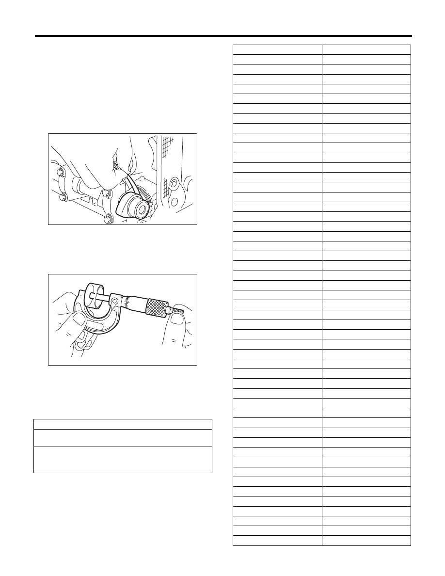
3) Remove the valve lifter.
4) Measure the thickness of valve lifter using mi-
crometer.

5) Select a valve lifter of suitable thickness from the
following table using the measured valve clearance
and valve lifter thickness, and install it.

NOTE:
Use a new valve lifter.

Unit: mm (in)

Intake valve: S = (V + T) – 0.20 (0.0079)
Exhaust valve: S = (V + T) – 0.35 (0.0138)

S: Valve lifter thickness required
V: Measured valve clearance
T: Valve lifter thickness to be used

ME-00024

ME-00025

Part No.

Thickness mm (in)

13228 AB102

4.68 (0.1843)

13228 AB112

4.69 (0.1846)

13228 AB122

4.70 (0.1850)

13228 AB132

4.71 (0.1854)

13228 AB142

4.72 (0.1858)

13228 AB152

4.73 (0.1862)

13228 AB162

4.74 (0.1866)

13228 AB172

4.75 (0.1870)

13228 AB182

4.76 (0.1874)

13228 AB192

4.77 (0.1878)

13228 AB202

4.78 (0.1882)

13228 AB212

4.79 (0.1886)

13228 AB222

4.80 (0.1890)

13228 AB232

4.81 (0.1894)

13228 AB242

4.82 (0.1898)

13228 AB252

4.83 (0.1902)

13228 AB262

4.84 (0.1906)

13228 AB272

4.85 (0.1909)

13228 AB282

4.86 (0.1913)

13228 AB292

4.87 (0.1917)

13228 AB302

4.88 (0.1921)

13228 AB312

4.89 (0.1925)

13228 AB322

4.90 (0.1929)

13228 AB332

4.91 (0.1933)

13228 AB342

4.92 (0.1937)

13228 AB352

4.93 (0.1941)

13228 AB362

4.94 (0.1945)

13228 AB372

4.95 (0.1949)

13228 AB382

4.96 (0.1953)

13228 AB392

4.97 (0.1957)

13228 AB402

4.98 (0.1961)

13228 AB412

4.99 (0.1965)

13228 AB422

5.00 (0.1969)

13228 AB432

5.01 (0.1972)

13228 AB442

5.02 (0.1976)

13228 AB452

5.03 (0.1980)

13228 AB462

5.04 (0.1984)

13228 AB472

5.05 (0.1988)

13228 AB482

5.06 (0.1992)

13228 AB492

5.07 (0.1996)

13228 AB502

5.08 (0.2000)

13228 AB512

5.09 (0.2004)

13228 AB522

5.10 (0.2008)

13228 AB532

5.11 (0.2012)

13228 AB542

5.12 (0.2016)

13228 AB552

5.13 (0.2020)

13228 AB562

5.14 (0.2024)

13228 AB572

5.15 (0.2028)

13228 AB582

5.16 (0.2031)

13228 AB592

5.17 (0.2035)

ME(H4DOTC)-29

Valve Clearance

MECHANICAL

6) Install the camshaft. <Ref. to ME(H4DOTC)-59,
INSTALLATION, Camshaft.>
7) Install the cam sprocket. <Ref. to ME(H4DOTC)-
56, INSTALLATION, Cam Sprocket.>
8) Install the timing belt. <Ref. to ME(H4DOTC)-50,
TIMING BELT, INSTALLATION, Timing Belt.>
9) Measure all valves for valve clearance again at
this time. If the valve clearance is not correct, re-
peat the procedure over again from the first step.
10) After measuring, install the related parts in the
reverse order of removal.

NOTE:
• Use a new rocker cover gasket.
• Use a new clamp for the PCV hose clamp, fit the
cut out in the ST with the protrusion on the clamp as
shown in the figure, and lock the clamp.
ST

18353AA000

CLAMP PLIERS

13228 AB602

5.18 (0.2039)

13228 AB612

5.19 (0.2043)

13228 AB622

5.20 (0.2047)

13228 AB632

5.21 (0.2051)

13228 AB642

5.22 (0.2055)

13228 AB652

5.23 (0.2059)

13228 AB662

5.24 (0.2063)

13228 AB672

5.25 (0.2067)

13228 AB682

5.26 (0.2071)

13228 AB692

5.27 (0.2075)

13228 AB702

4.38 (0.1724)

13228 AB712

4.40 (0.1732)

13228 AB722

4.42 (0.1740)

13228 AB732

4.44 (0.1748)

13228 AB742

4.46 (0.1756)

13228 AB752

4.48 (0.1764)

13228 AB762

4.50 (0.1771)

13228 AB772

4.52 (0.1780)

13228 AB782

4.54 (0.1787)

13228 AB792

4.56 (0.1795)

13228 AB802

4.58 (0.1803)

13228 AB812

4.60 (0.1811)

13228 AB822

4.62 (0.1819)

13228 AB832

4.64 (0.1827)

13228 AB842

4.66 (0.1835)

13228 AB852

5.29 (0.2083)

13228 AB862

5.31 (0.2091)

13228 AB872

5.33 (0.2098)

13228 AB882

5.35 (0.2106)

13228 AB892

5.37 (0.2114)

13228 AB902

5.39 (0.2122)

13228 AB912

5.41 (0.2123)

13228 AB922

5.43 (0.2138)

13228 AB932

5.45 (0.2146)

13228 AB942

5.47 (0.2154)

13228 AB952

5.49 (0.2161)

13228 AB962

5.51 (0.2169)

13228 AB972

5.53 (0.2177)

13228 AB982

5.55 (0.2185)

13228 AB992

5.57 (0.2193)

13228 AC002

5.59 (0.2201)

13228 AC012

5.61 (0.2209)

13228 AC022

5.63 (0.2217)

13228 AC032

5.65 (0.2224)

Part No.

Thickness mm (in)

ME-03630

ME(H4DOTC)-30

Engine Assembly

MECHANICAL

9. Engine Assembly

A: REMOVAL

1) Set the vehicle on a lift.
2) Open the front hood fully and support with the
front hood stay.
3) Remove the collector cover.
4) Collect the refrigerant from A/C system. <Ref. to
AC-22, Refrigerant Recovery Procedure.>
5) Release the fuel pressure. <Ref. to
FU(H4DOTC)-57, RELEASING OF FUEL PRES-
SURE, PROCEDURE, Fuel.>
6) Remove the battery. <Ref. to SC(H4SO)-20,
REMOVAL, Battery.>
7) Open the fuel filler lid, and remove the fuel filler cap.
8) Remove the air intake duct and air cleaner case.
<Ref. to IN(H4DOTC)-9, REMOVAL, Air Intake
Duct.> <Ref. to IN(H4DOTC)-8, REMOVAL, Air
Cleaner Case.>
9) Remove the intercooler. <Ref. to IN(H4DOTC)-
12, REMOVAL, Intercooler.>
10) Remove the radiator from vehicle. <Ref. to
CO(H4DOTC)-20, REMOVAL, Radiator.>
11) Remove the coolant filler tank. <Ref. to
CO(H4DOTC)-30, REMOVAL, Coolant Filler Tank.>
12) Disconnect the A/C pressure hoses from A/C com-
pressor. <Ref. to AC-40, REMOVAL, Hose and Pipe.>
13) Disconnect the bulkhead harness connectors
from the engine harness connectors.

14) Remove the engine harness connectors from
the engine harness brackets.

15) Disconnect the following connectors and termi-
nals.

(1) Generator connector and terminal

(2) A/C compressor connector

(3) Secondary air pump connector

16) Disconnect the following hoses.

(1) Brake booster vacuum hose

FU-02436

ME-03081

ME-03082

ME-03638

ME-03898

ME(H4DOTC)-31

Engine Assembly

MECHANICAL

(2) Heater inlet and outlet hoses

17) Remove the power steering pump.

(1) Remove the front side belts. <Ref. to
ME(H4DOTC)-41, FRONT SIDE BELT, RE-
MOVAL, V-belt.>
(2) Disconnect the power steering pump switch
connector.

(3) Remove the power steering pump from the
engine. <Ref. to PS-44, REMOVAL, Oil Pump.>

(4) Place the power steering pump on the right
side wheel apron.

18) Lift up the vehicle.
19) Remove the center exhaust pipe. <Ref. to
EX(H4DOTC)-7, REMOVAL, Center Exhaust
Pipe.>
20) Remove the turbocharger. <Ref. to
IN(H4DOTC)-14, REMOVAL, Turbocharger.>
21) Remove the joint pipe and front exhaust pipe.
<Ref. to EX(H4DOTC)-11, REMOVAL, Joint Pipe.>
<Ref. to EX(H4DOTC)-5, REMOVAL, Front Ex-
haust Pipe.>
22) Lift up the vehicle.

23) Disconnect the ground cable on the engine
side.

24) Remove the bolts and nuts which hold the low-
er side of transmission to the engine.
• AT model

• MT model

25) Remove the nuts which hold the engine mount
to the front crossmember.

26) Lower the vehicle.

ME-03701

FU-03022

ME-03083

ME-03702

AT-03238

MT-00077

ME-03703


Content   ..  260  261  262  263   ..