Subaru Legacy IV (2008 year). Manual - part 167
EN(H4SO)(diag)-271
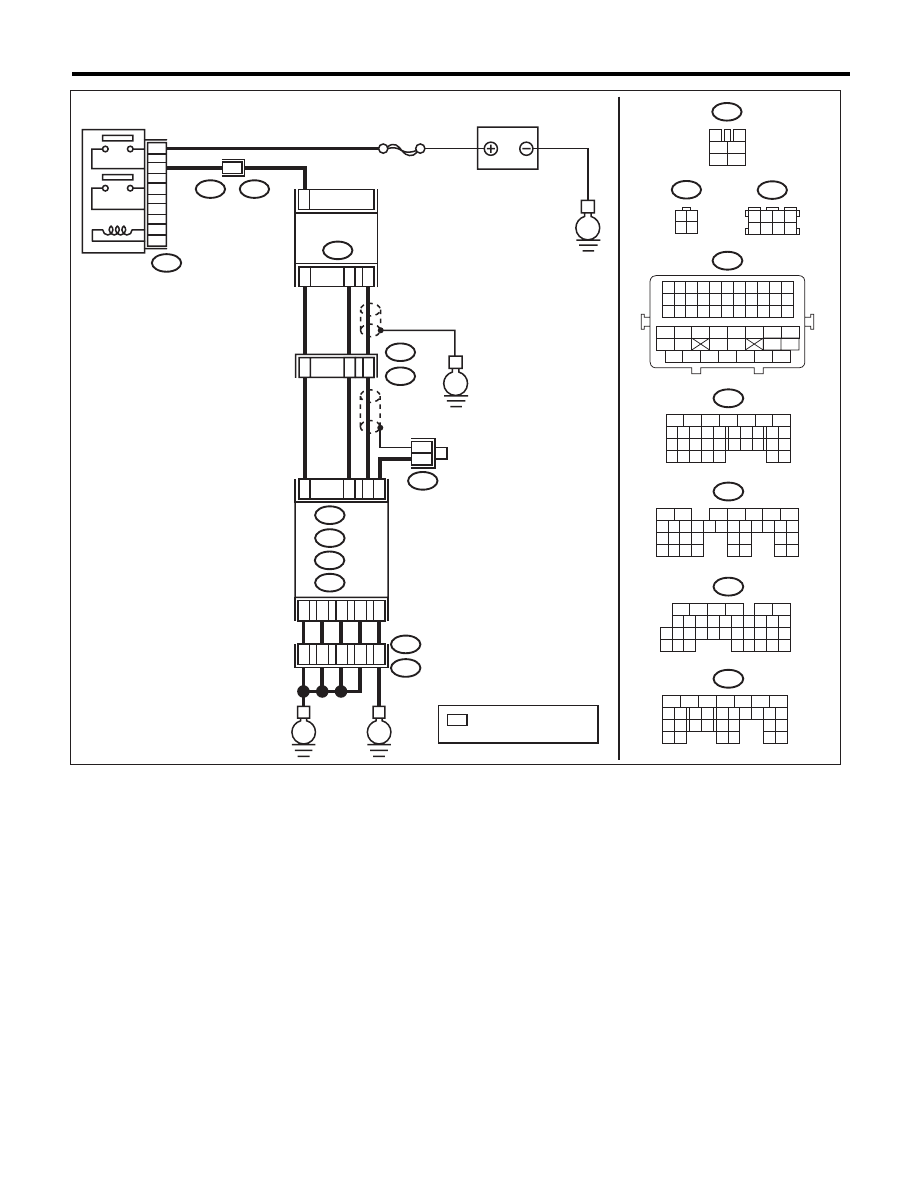
Diagnostic Procedure with Diagnostic Trouble Code (DTC)
ENGINE (DIAGNOSTICS)
EN-06836
A5
D1
D2
D3
D7
36
34
35
37
52
ECM
B21
B138
E2
B135
B:
D: B137
C: B136
E
E
A: B134
B137
5
6
7
8
2
1
9
4
3
10
22 23
11 12 13 14 15
24 25
26
16 17
18 19 20 21
27
28 29
30 31
B134
5
6
7
8
2
1
9
4
3
10
24
22 23
25
11 12 13 14 15
26 27
28
16 17
18 19 20 21
33 34
29
32
30 31
B136
5
6
7 8
2
1
9
4
3
10
24
22 23
25
11 12 13 14 15
26 27
28
16
17 18 19 20 21
33 34
29
32
30
31
35
B135
5
6
7
8
2
1
9
4
3
10
24
22 23
25
11 12 13 14 15
26 27
28
16 17 18 19
20 21
29 30 31
32 33
34 35
A:
B:
C:
D:
*
*
3
4
1
2
5
6
B327
SBF-5
E
B327
E23
6
4
5
3
2
1
1
B21
E2
50
53
1
19
E2
B21
E
E23
BATTERY
REAR OXYGEN
SENSOR
A/F, OXYGEN
SENSOR RELAY
1
3 4
2
2
3
4
B1
B4
A29
C4
B138
3 4
5 6
1 2
7 8
B21
1 2 3 4 5 6 7 8 9 10 11
12 13 14 15 16 17 18 19 20 21 22
23 24 25 26 27 28 29 30 31 32 33
34
35
42
43
36
37
38
39
48
49
50
51
52
53
54
40
41
44
45
46
47
: TERMINAL No. OPTIONAL
ARRANGEMENT
*