Content .. 1106 1107 1108 1109 ..
Subaru Legacy IV (2008 year). Manual - part 1108
SL-5
General Description
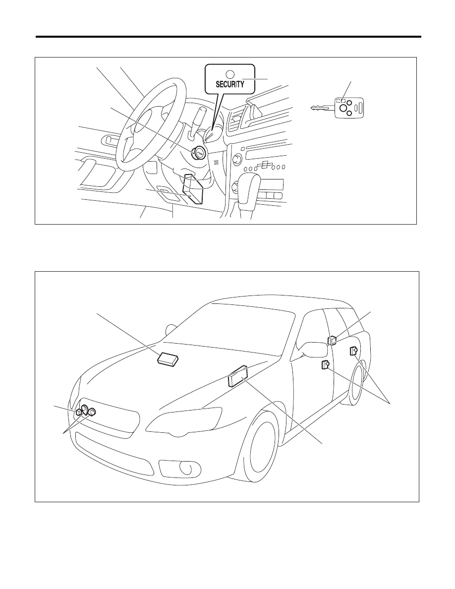
SECURITY AND LOCKS
4. IMMOBILIZER SYSTEM
5. KEYLESS ENTRY SYSTEM
(1)
Antenna
(3)
Body integrated unit
(4)
Transponder
(2)
Security indicator light (LED bulb)
(1)
Keyless entry control module
(3)
Door switch
(5)
Horn
(2)
Rear gate latch switch (wagon
model), Trunk lid switch (sedan
model)
(4)
Body integrated unit
(6)
Keyless buzzer
(2)
(4)
(1)
(3)
SL-00686
SL-00702
(3)
(2)
(4)
(1)
(5)
(6)