Subaru Legacy IV (2008 year). Manual - part 1106


  Index      Subaru     Subaru Legacy IV - service repair manual 2008 year


Search            


Content   ..  1104  1105  1106  1107   ..


Subaru Legacy IV (2008 year). Manual - part 1106


SE-36

Power Seat System

SEATS

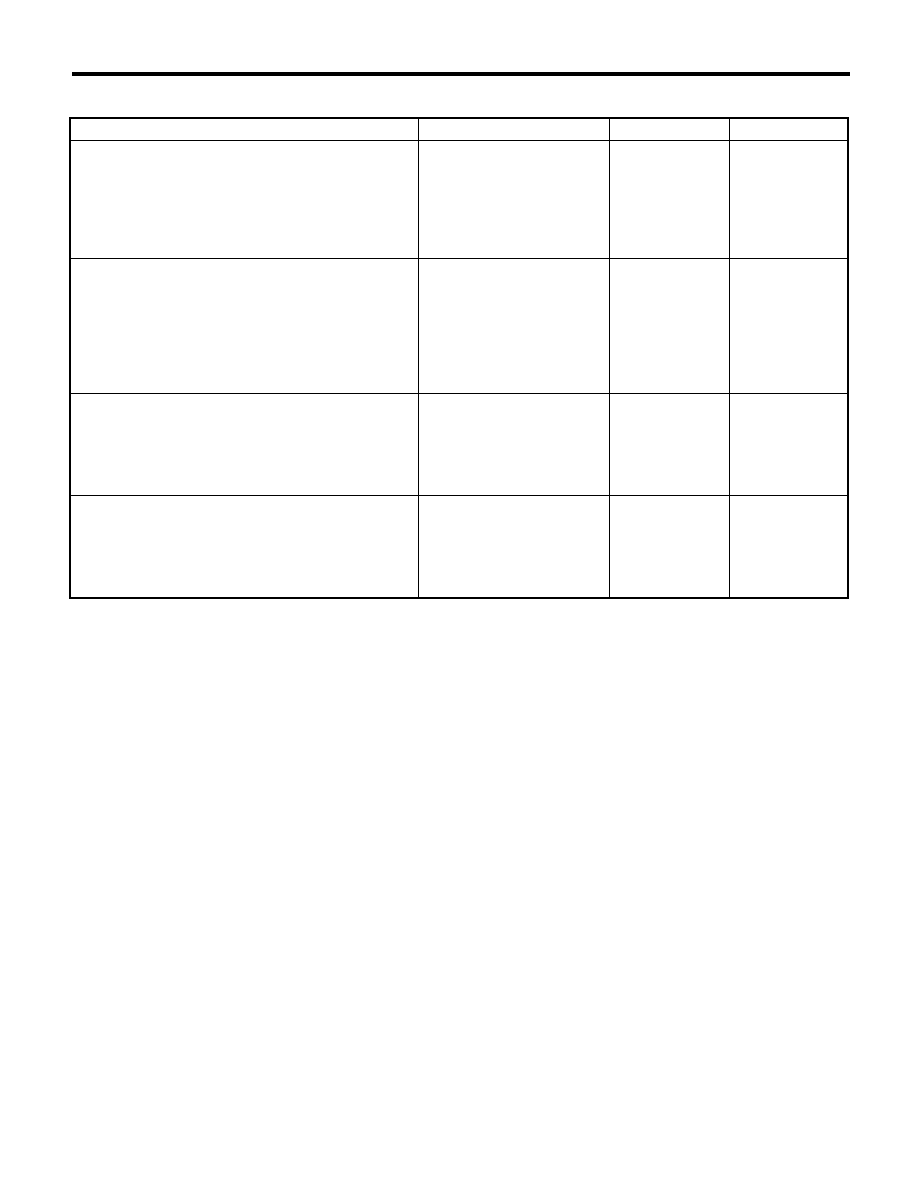
9. FAILS TO STORE THE LOCATION TO THE MEMORY (DRIVER’S SEAT, WITH MEMORY)

Step

Check

Yes

No

1

CHECK SWITCH.
1) Disconnect the harness connector of mem-
ory switch assembly.
2) Check memory switch. <Ref. to SE-28, 
CHECK MEMORY SWITCH (MEMORY-
EQUIPPED), INSPECTION, Power Seat Sys-
tem.>

Is there any problem on the 
inspection result?

Go to step 2.

Replace the mem-
ory switch assem-
bly.

2

CHECK HARNESS.
Measure the resistance between the memory 
switch connector and memory module connec-
tor.

Connector & terminal

(R195) No. 13 — (R198) No. 3:
(R195) No. 14 — (R198) No. 2:
(R195) No. 15 — (R198) No. 8:

Is the resistance less than 10 

:? Go to step 3.

Check power seat 
harness.

3

CHECK COMBINATION METER.
Turn the ignition switch to ON and check the 
indicator inside the meter while the selector 
lever is in P position.

Does the indicator display P?

Go to step 4.

Check the combi-
nation meter. <Ref. 
to IDI-5, INSPEC-
TION, Combina-
tion Meter 
System.>

4

SYSTEM INITIALIZATION.
Initialize memory seat system. <Ref. to SE-40, 
ADJUSTMENT, Power Seat System.>

Is the initialization completed 
successfully?

Replace the mem-
ory module.

<Ref. to SE-38, 
INITIALIZATION IS 
IMPOSSIBLE,
INSPECTION,
Power Seat Sys-
tem.>

SE-37

Power Seat System

SEATS

10.FAILS TO PERFORM THE REPLAY OPERATION (DRIVER’S SEAT, WITH MEMORY)

Step

Check

Yes

No

1

CHECK MEMORY FUNCTION.
Perform the memory operation of the seat posi-
tion, and check the memory replay operation.

Does the seat position memory 
replay correctly?

Memory function is 
normal. Memory 
seems to be 
cleared since volt-
age was less from 
the operation-
ensured voltage 
temporary at the 
time of memory 
restoring and man-
ual operation. It 
operates normally 
by registering a 
memory.

Go to step 2.

2

CHECK MEMORY FUNCTION.
At the step 1 memory operation, check the beep 
sound (once).

Check the beep sound?

Go to step 3.

<Ref. to SE-36, 
FAILS TO STORE 
THE LOCATION 
TO THE MEMORY 
(DRIVER’S SEAT, 
WITH MEMORY), 
INSPECTION,
Power Seat Sys-
tem.>

3

CHECK SWITCH.
1) Disconnect the harness connector of mem-
ory switch assembly.
2) Check memory switch. <Ref. to SE-28, 
CHECK MEMORY SWITCH (MEMORY-
EQUIPPED), INSPECTION, Power Seat Sys-
tem.>

Is there any problem on the 
inspection result?

Go to step 4.

Replace the mem-
ory switch assem-
bly.

4

CHECK HARNESS.
Measure the resistance between the memory 
switch connector and memory module connec-
tor.

Connector & terminal

(R195) No. 13 — (R198) No. 3:
(R195) No. 14 — (R198) No. 2:
(R195) No. 15 — (R198) No. 8:

Is the resistance less than 10 

:? Go to step 5.

Check power seat 
harness.

5

CHECK COMBINATION METER.
Turn the ignition switch to ON and check the 
indicator light inside the meter.
• AT model: when the select lever is in “P” posi-
tion
• MT model: when the parking brake lever is 
pulled

Is indicator light displayed?

Go to step 6.

Check the combi-
nation meter. <Ref. 
to IDI-5, INSPEC-
TION, Combina-
tion Meter 
System.>

6

CHECK OPERATION.
Check the rotation of each motor when perform-
ing all the power seat switch operation.

Does each motor rotate for one 
second or more when operating 
each switch?

Replace the mem-
ory module.

Encoder defec-
tion. Replace the 
appropriate motor.

SE-38

Power Seat System

SEATS

11.INITIALIZATION IS IMPOSSIBLE

12.ALL FUNCTION FAILS TO OPERATE (PASSENGER’S SEAT)

Step

Check

Yes

No

1

CHECK OPERATION.
Check the rotation of each motor when perform-
ing all the power seat switch operation.

Does each motor rotate for one 
second or more when operating 
each switch?

Go to step 2.

Encoder defec-
tion. Replace the 
appropriate motor.

2

CHECK SWITCH.
1) Disconnect the harness connector of power 
seat switch assembly.
2) Measure resistance between all terminals of 
power seat switch assembly. <Ref. to SE-27, 
CHECK POWER SEAT SWITCH, INSPEC-
TION, Power Seat System.>

Is there any problem on the 
inspection result?

Replace the mem-
ory module.

Replace the power 
seat switch assem-
bly.

Step

Check

Yes

No

1

CHECK SEAT FUNCTION.
Operate each power seat switch and check that 
each power seat function operates normally.

Does all function fails to oper-
ate?

Go to step 2.

Check the motor 
which does not 
operate. <Ref. to 
SE-39, SOME OF 
THE MOTORS DO 
NOT OPERATE 
(PASSENGER’S 
SEAT), INSPEC-
TION, Power Seat 
System.>

2

CHECK FUSE.
Check the power seat fuse inside the fuse box.

Is the fuse blown out?

Replace the appro-
priate fuse.

Go to step 3.

3

CHECK POWER SUPPLY CIRCUIT.
1) Disconnect the connector of power seat 
switch assembly.
2) Measure the voltage between harness con-
nector and chassis ground.

Connector & terminal

(R200) No. 7 (+) — Chassis ground (–):

Is the voltage 10 V or more?

Go to step 4.

Check body har-
ness.

4

CHECK POWER SUPPLY CIRCUIT.
Measure the resistance between power seat 
switch harness connector and chassis ground.

Connector & terminal

(R200) No. 8 — Chassis ground:

Is the resistance less than 10 

:? Replace the power 

seat switch assem-
bly.

Check body har-
ness.

SE-39

Power Seat System

SEATS

13.SOME OF THE MOTORS DO NOT OPERATE (PASSENGER’S SEAT)

• Malfunction of slide operation

• Malfunction of reclining operation

Step

Check

Yes

No

1

CHECK SWITCH.
1) Disconnect the connector of power seat 
switch assembly.
2) Measure resistance between terminals 
while moving the switch to slide forward and 
slide rearward positions. <Ref. to SE-27, 
CHECK POWER SEAT SWITCH, INSPEC-
TION, Power Seat System.>

Is there any problem on the 
inspection result?

Go to step 2.

Replace the power 
seat switch assem-
bly.

2

CHECK HARNESS.
1) Disconnect the power seat switch connector 
and slide motor connector.
2) Measure the resistance between power 
seat switch connector and slide motor connec-
tor.

Connector & terminal

(R202) No. 1 — (R200) No. 13:
(R202) No. 2 — (R200) No. 14:

Is the resistance less than 10 

:? Go to step 3.

Check power seat 
harness.

3

CHECK SLIDE MOTOR.
1) Connect the power seat switch connector 
and slide motor connector.
2) Apply 12 V voltage to the slide motor and 
check the motor rotation.

Connector & terminal

(R200) No. 14 (+) — (R200) No. 13 (–):
(R200) No. 13 (+) — (R200) No. 14 (–):

Does the motor rotate nor-
mally?

Check for tempo-
rary poor contact 
or mechanical 
trouble in slide rail.

Slide motor prob-
lem. Replace the 
slide motor assem-
bly.

Step

Check

Yes

No

1

CHECK SWITCH.
1) Disconnect the connector of power seat 
switch assembly.
2) Measure resistance between terminals 
while moving the switch to reclining forward and 
reclining rearward positions. <Ref. to SE-27, 
CHECK POWER SEAT SWITCH, INSPEC-
TION, Power Seat System.>

Is there any problem on the 
inspection result?

Go to step 2.

Replace the power 
seat switch assem-
bly.

2

CHECK HARNESS.
1) Disconnect the power seat switch connector 
and reclining motor connector.
2) Measure the resistance between power 
seat switch connector and reclining motor con-
nector.

Connector & terminal

(R201) No. 2 — (R200) No. 4:
(R201) No. 1 — (R200) No. 3:

Is the resistance less than 10 

:? Go to step 3.

Check power seat 
harness.

3

CHECK RECLINING MOTOR.
1) Connect the power seat switch connector 
and reclining motor connector.
2) Apply 12 V voltage to the reclining motor 
and check the motor rotation.

Connector & terminal

(R200) No. 3 (+) — (R200) No. 4 (–):
(R200) No. 4 (+) — (R200) No. 3 (–):

Does the motor rotate nor-
mally?

Check for tempo-
rary poor contact 
or mechanical 
trouble in reclining 
hinge.

Reclining motor 
problem. Replace 
the reclining motor 
assembly.


Content   ..  1104  1105  1106  1107   ..