Subaru Legacy IV (2008 year). Manual - part 1104


  Index      Subaru     Subaru Legacy IV - service repair manual 2008 year


Search            


Content   ..  1102  1103  1104  1105   ..


Subaru Legacy IV (2008 year). Manual - part 1104


SE-28

Power Seat System

SEATS

• Passenger’s seat

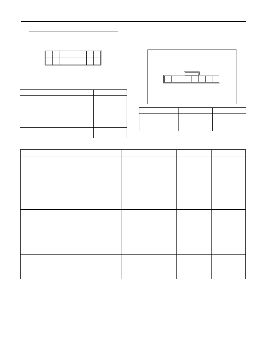
4. CHECK MEMORY SWITCH 
(MEMORY-EQUIPPED)

Move each switch and measure the resistance be-
tween connector terminals.

5. ALL FUNCTION FAILS TO OPERATE (DRIVER’S SEAT, WITHOUT MEMORY)

Switch position

Terminal No.

Standard

Slide forward

7 and 13
8 and 14

Less than 10 

:

Slide backward

7 and 14
8 and 13

Less than 10 

:

Reclining forward

7 and 4
8 and 3

Less than 10 

:

Reclining backward

7 and 3
8 and 4

Less than 10 

:

5 4

3

8 7

6

2 1

11

9

10

12

14 13

SE-00682

Switch position

Terminal No.

Standard

Memory 1

3 and 1

Less than 10 

:

Memory 2

2 and 1

Less than 10 

:

Set

8 and 1

Less than 10 

:

5 4 3

8 7 6

2 1

SE-00683

Step

Check

Yes

No

1

CHECK SEAT FUNCTION.
Operate each power seat switch and check that 
each power seat function operates normally.

Does all function fails to oper-
ate?

Go to step 2.

Check motors that 
do not operate. 
<Ref. to SE-29, 
SOME OF THE 
MOTORS DO NOT 
OPERATE 
(DRIVER’S SEAT, 
WITHOUT MEM-
ORY), INSPEC-
TION, Power Seat 
System.>

2

CHECK FUSE.
Check the power seat fuse inside the fuse box.

Is the fuse blown out?

Replace the appro-
priate fuse.

Go to step 3.

3

CHECK POWER SUPPLY CIRCUIT.
1) Disconnect the connector of power seat 
switch assembly.
2) Measure the voltage between harness con-
nector and chassis ground.

Connector & terminal

(R190) No. 7 (+) — Chassis ground (–):

Is the voltage 10 V or more?

Go to step 4.

Check body har-
ness.

4

CHECK POWER SUPPLY CIRCUIT.
Measure the resistance between power seat 
switch harness connector and chassis ground.

Connector & terminal

(R190) No. 8 — Chassis ground:

Is the resistance less than 10 

:? Replace the power 

seat switch assem-
bly.

Check body har-
ness.

SE-29

Power Seat System

SEATS

6. SOME OF THE MOTORS DO NOT OPERATE (DRIVER’S SEAT, WITHOUT MEMORY)

• Malfunction of slide operation

• Malfunction of tilt operation

Step

Check

Yes

No

1

CHECK SWITCH.
1) Disconnect the connector of power seat 
switch assembly.
2) Measure resistance between terminals 
while moving the switch to slide forward and 
slide rearward positions. <Ref. to SE-27, 
CHECK POWER SEAT SWITCH, INSPEC-
TION, Power Seat System.>

Is there any problem on the 
inspection result?

Go to step 2.

Replace the power 
seat switch assem-
bly.

2

CHECK HARNESS.
1) Disconnect the power seat switch connector 
and slide motor connector.
2) Measure the resistance between power 
seat switch connector and slide motor connec-
tor.

Connector & terminal

(R192) No. 1 — (R190) No. 14:
(R192) No. 2 — (R190) No. 13:

Is the resistance less than 10 

:? Go to step 3.

Check power seat 
harness.

3

CHECK SLIDE MOTOR.
1) Connect the power seat switch connector 
and slide motor connector.
2) Apply 12 V voltage to the slide motor and 
check the motor rotation.

Connector & terminal

(R190) No. 14 (+) — (R190) No. 13 (–):
(R190) No. 13 (+) — (R190) No. 14 (–):

Does the motor rotate nor-
mally?

Check for tempo-
rary poor contact 
or mechanical 
trouble in slide rail.

Slide motor prob-
lem. Replace the 
slide rail assembly.

Step

Check

Yes

No

1

CHECK SWITCH.
1) Disconnect the connector of power seat 
switch assembly.
2) Measure resistance between terminals 
while moving the switch to tilt up and tilt down 
positions. <Ref. to SE-27, CHECK POWER 
SEAT SWITCH, INSPECTION, Power Seat 
System.>

Is there any problem on the 
inspection result?

Go to step 2.

Replace the power 
seat switch assem-
bly.

2

CHECK HARNESS.
1) Disconnect the power seat switch connector 
and tilt motor connector.
2) Measure the resistance between power 
seat switch connector and tilt motor connector.

Connector & terminal

(R197) No. 2 — (R190) No. 2:
(R197) No. 3 — (R190) No. 1:

Is the resistance less than 10 

:? Go to step 3.

Check power seat 
harness.

3

CHECK TILT MOTOR.
1) Connect the power seat switch connector 
and tilt motor connector.
2) Apply 12 V voltage to the tilt motor and 
check the motor rotation.

Connector & terminal

(R190) No. 2 (+) — (R190) No. 1 (–):
(R190) No. 1 (+) — (R190) No. 2 (–):

Does the motor rotate nor-
mally?

Check for tempo-
rary poor contact 
or mechanical 
trouble in tilt mech-
anism.

Tilt motor problem. 
Replace the slide 
rail assembly.

SE-30

Power Seat System

SEATS

• Malfunction of lifter operation

• Malfunction of reclining operation

Step

Check

Yes

No

1

CHECK SWITCH.
1) Disconnect the connector of power seat 
switch assembly.
2) Measure resistance between terminals 
while moving the switch to lifter up and lifter 
down positions. <Ref. to SE-27, CHECK 
POWER SEAT SWITCH, INSPECTION, Power 
Seat System.>

Is there any problem on the 
inspection result?

Go to step 2.

Replace the power 
seat switch assem-
bly.

2

CHECK HARNESS.
1) Disconnect the power seat switch connector 
and lifter motor connector.
2) Measure the resistance between power 
seat switch connector and lifter motor connec-
tor.

Connector & terminal

(R194) No. 4 — (R190) No. 5:
(R194) No. 3 — (R190) No. 6:

Is the resistance less than 10 

:? Go to step 3.

Check power seat 
harness.

3

CHECK LIFTER MOTOR.
1) Connect the power seat switch connector 
and lifter motor connector.
2) Apply 12 V voltage to the lifter motor and 
check the motor rotation.

Connector & terminal

(R190) No. 5 (+) — (R190) No. 6 (–):
(R190) No. 6 (+) — (R190) No. 5 (–): 

Does the motor rotate nor-
mally?

Check for tempo-
rary poor contact 
or mechanical 
trouble in lifter 
mechanism.

Lifter motor prob-
lem. Replace the 
slide rail assembly.

Step

Check

Yes

No

1

CHECK SWITCH.
1) Disconnect the connector of power seat 
switch assembly.
2) Measure resistance between terminals 
while moving the switch to reclining forward and 
reclining rearward positions. <Ref. to SE-27, 
CHECK POWER SEAT SWITCH, INSPEC-
TION, Power Seat System.>

Is there any problem on the 
inspection result?

Go to step 2.

Replace the power 
seat switch assem-
bly.

2

CHECK HARNESS.
1) Disconnect the power seat switch connector 
and reclining motor connector.
2) Measure the resistance between power 
seat switch connector and reclining motor con-
nector.

Connector & terminal

(R191) No. 2 — (R190) No. 3:
(R191) No. 1 — (R190) No. 4:

Is the resistance less than 10 

:? Go to step 3.

Check power seat 
harness.

3

CHECK RECLINING MOTOR.
1) Connect the power seat switch connector 
and reclining motor connector.
2) Apply 12 V voltage to the reclining motor 
and check the motor rotation.

Connector & terminal

(R190) No. 3 (+) — (R190) No. 4 (–):
(R190) No. 4 (+) — (R190) No. 3 (–):

Does the motor rotate nor-
mally?

Check for tempo-
rary poor contact 
or mechanical 
trouble in reclining 
hinge.

Reclining motor 
problem. Replace 
the reclining motor 
assembly.

SE-31

Power Seat System

SEATS

7. DOES NOT OPERATE IN MANUAL OPERATION (DRIVER’S SEAT, MEMORY-EQUIPPED)

Step

Check

Yes

No

1

CHECK SEAT FUNCTION.
Operate each power seat switch and check that 
each power seat function operates normally.

Does all function fails to oper-
ate?

Go to step 2.

Check the motor 
which does not 
operate. <Ref. to 
SE-32, SOME OF 
THE MOTORS DO 
NOT OPERATE. 
(DRIVER’S SEAT, 
WITH MEMORY), 
INSPECTION,
Power Seat Sys-
tem.>

2

CHECK FUSE.
Check the power seat fuse inside the fuse box.

Is the fuse blown out?

Replace the appro-
priate fuse.

Go to step 3.

3

CHECK POWER SUPPLY CIRCUIT.
1) Disconnect the memory module connector.
2) Measure the voltage between harness con-
nector and chassis ground.

Connector & terminal

(R195) No. 10 (+) — Chassis ground (–):
(R196) No. 8 (+) — Chassis ground (–):
(R196) No. 3 (+) — Chassis ground (–):

Is the voltage 10 V or more?

Go to step 4.

Check body har-
ness.

4

CHECK POWER SUPPLY CIRCUIT.
Measure the resistance between memory mod-
ule harness connector and chassis ground.

Connector & terminal

(R196) No. 14 — Chassis ground:
(R196) No. 12 — Chassis ground:

Is the resistance less than 10 

:? Go to step 5.

Check body har-
ness.

5

CHECK IGNITION CIRCUIT.
Measure the voltage between harness connec-
tor and chassis ground while turning the ignition 
switch to ON.

Connector & terminal

(R195) No. 11 (+) — Chassis ground (–):

Is the voltage 10 V or more?

Go to step 6.

Check body har-
ness.

6

CHECK TRANSMISSION CIRCUITS.
Measure the resistance between harness con-
nector and chassis ground in the following con-
dition.
• AT model: Select lever shifted to P position.
• MT model: Parking brake lever pulled.

Connector & terminal

(R195) No. 12 — Chassis ground:

Is the resistance less than 10 

:? Go to step 7.

Check body har-
ness.

7

CHECK SWITCH.
1) Disconnect the connector of power seat 
switch assembly.
2) Measure resistance between terminals 
while moving the switch to reclining forward and 
reclining rearward positions. <Ref. to SE-27, 
CHECK POWER SEAT SWITCH, INSPEC-
TION, Power Seat System.>

Is there any problem on the 
inspection result?

Replace the mem-
ory module.

Replace the power 
seat switch assem-
bly.


Content   ..  1102  1103  1104  1105   ..