Content .. 1057 1058 1059 1060 ..
Subaru Legacy IV (2008 year). Manual - part 1059
WW-12
Wiper Blade
WIPER AND WASHER SYSTEMS
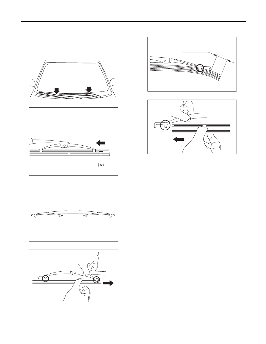
D: ASSEMBLY
1. FRONT
1) Insert the wiper rubber onto the blade so that the
stopper is in the position shown in the figure.
2) Make sure the wiper rubber is securely fastened
to the pull stopper (A).
2. REAR
1) Insert the wiper rubber into claw B.
2) Insert the wiper rubber until its top end protrudes
approx. 20 mm (0.79 in) from stopper D.
3) Insert the wiper rubber into claw A.
E: INSPECTION
1) When the wiper does not operate properly, in-
spect the following item.
• Make sure the movable part of wiper blade as-
sembly moves smoothly.
• Make sure the wiper rubber is not deformed or
damaged.
2) If damaged, replace with a new part.
WW-00440
WW-00037
WW-00421
A
B
C
D
WW-00145
A
B
WW-00146
D
20 mm ( 0.79 in. )
A
WW-00147