Subaru Legacy IV (2008 year). Manual - part 1058


  Index      Subaru     Subaru Legacy IV - service repair manual 2008 year


Search            


Content   ..  1056  1057  1058  1059   ..


Subaru Legacy IV (2008 year). Manual - part 1058


WW-8

Combination Switch (Wiper)

WIPER AND WASHER SYSTEMS

2. FRONT WIPER

1) Check with Subaru Select Monitor
When the front wiper switch is operated, check the
input signal using the Subaru Select Monitor.

(1) Prepare the Subaru Select Monitor kit. <Ref.
to GW-7, PREPARATION TOOL, General De-
scription.>
(2) Turn the ignition switch to ON (engine OFF)
and run the “PC application for Subaru Select
Monitor”.
(3) On the «System Selection Menu» display,
select the {Integ. unit mode}.
(4) Select the {Current Data Display & Save}.
(5) Check the input signal when the front wiper
switch is set to LO or HI.

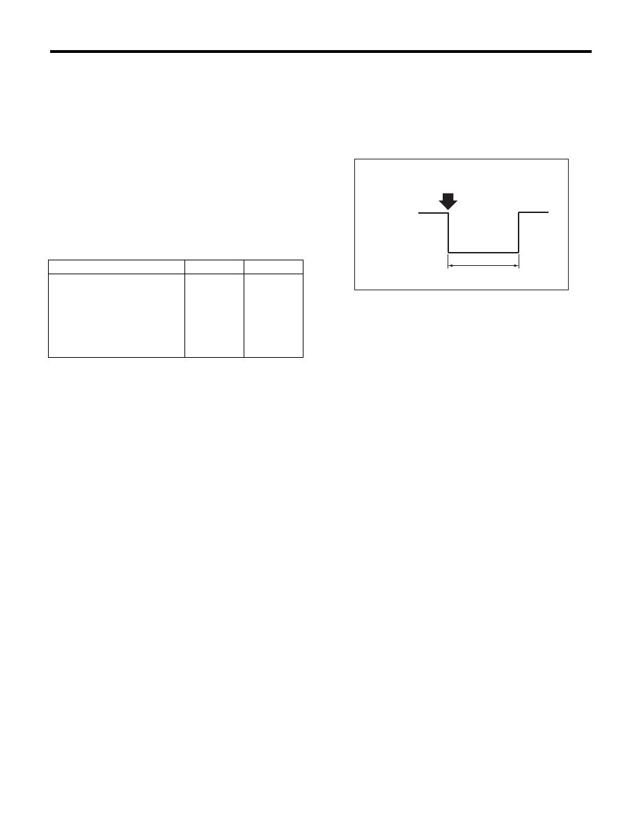
2) Check the intermittent operation (inspection of
the wiper switch alone)

(1) Set the voltage meter between connector
terminal No. 7 (+) and No. 2 (–).
(2) Connect the battery to connector. (Terminal
No. 17 — (+), terminal No. 2 & 16 — (–) )
(3) Turn the wiper switch to INT.
(4) Connect the battery (+) to the terminal No.
16 for 5 seconds.
(5) Connect the battery (–) to the terminal No.
16, and check the voltage between terminal No.
7 — No. 2 when performing the intermittent op-
eration.

(6) Perform step (1) to (5) above when intermit-
tent control switch is in MIN or MAX, and re-
place the switch if the operation is not as
specified.

Intermittent stationary time

MIN: Approx. 2 seconds
MAX: Approx. 16 seconds

Check

Yes

No

Is the input signal normal?

Finish the 
diagnosis.

Replace the 
body inte-
grated unit.
<Ref. to SL-
56, Body 
Integrated 
Unit.>

(A): Connect the battery (–) to the terminal No. 16.

S: Intermittent downtime (sec.)

WW-00393

(A)

S

12 V

0 V

WW-9

Combination Switch (Wiper)

WIPER AND WASHER SYSTEMS

3. REAR WIPER

1) Check with Subaru Select Monitor

Step

Check

Yes

No

1

CHECK INPUT OF REAR WIPER SWITCH.
Check the input from body integrated unit using 
the Subaru Select Monitor.
1) Prepare the Subaru Select Monitor kit.
2) Turn the ignition switch to ON.
3) On the «System Selection Menu» display, 
select the {Integ. unit mode}.
4) Select the {Current Data Display & Save}.
5) Check the input of the rear wiper switch.

Is the input normal?

Go to step 4.

Go to step 2.

2

CHECK HARNESS.
1) Disconnect the ground cable from battery.
2) Disconnect the connector of body inte-
grated unit.
3) Disconnect the connector from wiper 
switch.
4) Measure the resistance between body inte-
grated unit and wiper switch.

Connector & terminal

(B281) No. 18 — (B70) No. 13:
(B281) No. 27 — (B70) No. 12:
(B281) No. 6 — (B70) No. 10:

Is the resistance less than 10 
:?

Go to step 3.

Repair the harness 
between the body 
integrated unit and 
wiper switch.

3

CHECK INPUT VOLTAGE OF BODY INTE-
GRATED UNIT.
1) Connect the ground cable to battery.
2) Turn the ignition switch to ACC.
3) Check the input voltage of body integrated 
unit.

Connector & terminal

(B280) No. 7 (+) — Chassis ground (–):

Is the voltage 10 V or more?

Go to step 4.

Check the harness 
and fuse.

4

CHECK OUTPUT OF BODY INTEGRATED 
UNIT.
When the rear wiper switch is operated, check 
the output using the Subaru Select Monitor.
1) Turn the ignition switch to ON.
2) Operate the rear wiper switch and set to 
each position of ON and INT.
3) At this time, check the body integrated unit 
output.

When set to ON, is ON output 
continuous? When set to INT, is 
ON/OFF output repeated? (INT 
OFF time (when vehicle 
parked): 12 seconds)

Check the rear 
wiper motor circuit.

Replace the body 
integrated unit. 
<Ref. to SL-56, 
Body Integrated 
Unit.>

WW-10

Combination Switch (Wiper)

WIPER AND WASHER SYSTEMS

2) Check rear wiper motor circuit

Step

Check

Yes

No

1

CHECK POWER SUPPLY CIRCUIT OF THE 
REAR WIPER MOTOR.
1) Disconnect the harness connector of the 
rear wiper motor.
2) Turn the ignition switch to ACC.
3) Measure the voltage between the rear wiper 
motor harness connector terminal and chassis 
ground.

Connector & terminal

(D43) No. 3 (+) — Chassis ground (–):

Is the voltage 10 V or more?

Go to step 2.

• Check the fuse 
(No. 23 in fuse & 
relay box).
• Check the fus-
ible link (No. 7 in 
main fuse box).

2

CHECK GROUND CIRCUIT OF REAR WIPER 
MOTOR.
1) Turn the ignition switch to OFF.
2) Measure the resistance between the rear 
wiper motor harness connector terminal and 
chassis ground.

Connector & terminal

(D43) No. 3 — Chassis ground:

Is the resistance less than 10 

:? Go to step 3.

Repair the open 
circuit of the rear 
wiper motor 
ground circuit.

3

CHECK HARNESS BETWEEN BODY INTE-
GRATED UNIT AND REAR WIPER MOTOR.
1) Turn the ignition switch to OFF.
2) Disconnect the harness connector of body 
integrated unit.
3) Disconnect the harness connector of the 
rear wiper motor.
4) Measure the resistance between the har-
ness connector terminals of the body integrated 
unit and rear wiper motor.

Connector & terminal

(B280) No. 1 — (D43) No. 2:
(B280) No. 8 — (D43) No. 4:

Is the resistance less than 10 

:? Go to step 4.

Repair the open 
circuit of the har-
ness between 
body integrated 
unit and rear wiper 
motor.

4

CHECK INPUT VOLTAGE OF BODY INTE-
GRATED UNIT.
1) Turn the ignition switch to ACC.
2) Check the input voltage of body integrated 
unit.

Connector & terminal

(B280) No. 21 (+) — Chassis ground (–):

Is the voltage 10 V or more?

Go to step 5.

Check the harness 
and fuse.

5

CHECK OUTPUT OF BODY INTEGRATED 
UNIT.
1) Connect the harness connector of body 
integrated unit.
2) Disconnect the connector of the rear wiper 
motor.
3) Turn the ignition switch to ACC.
4) Measure the voltage between rear wiper 
motor connector and chassis ground.

Connector & terminal

(D43) No. 1 (+) — Chassis ground (–):

Is the voltage 1.5 V or less 
when rear wiper switch is to 
OFF? / Is the voltage 10 V or 
more when rear wiper switch is 
to ON?

Go to step 6.

Replace the body 
integrated unit. 
<Ref. to SL-56, 
Body Integrated 
Unit.>

6

CHECK OPERATION OF REAR WIPER MO-
TOR.
1) Remove the rear wiper motor.
2) Check the rear wiper motor. <Ref. to WW-
18, INSPECTION, Rear Wiper Motor.>

Does the rear wiper motor 
rotate normally?

End.

Replace the rear 
wiper motor.

WW-11

Wiper Blade

WIPER AND WASHER SYSTEMS

4. Wiper Blade

A: REMOVAL

CAUTION:
When replacing the wiper blade, if standing up
the wiper arm, be sure to stand up the driver’s
side wiper arm first, and then passenger’s side
wiper arm next. Also, when putting the wiper
arms back, be sure to start with passenger’s
side first, then driver’s side next. Doing this in
the reverse order may result in the driver’s side
wiper blade hitting the passenger’s side wiper
arm and causing damage.

1. FRONT

While pushing the locking clip (A) up, pull out the
blade to the direction of the arrow and remove it
from the wiper arm.

2. REAR

Turn the blade in the direction of arrow (A) and re-
move it from arm.

B: INSTALLATION

1) Install in the reverse order of removal.
2) Confirm that the clip is locked securely.

C: DISASSEMBLY

1. FRONT

Pull side (A) of the wiper rubber stopper and re-
move the rubber from the blade assembly.

2. REAR

Pull the wiper rubber top slightly from stopper (A)
and pull out completely.

(A) Turn the wiper blade.

(1) Wiper arm

(2) Wiper blade

(3) Wiper blade attachment section

WW-00064

1

2

2

3

3

(A)

(1)

(2)

(3)

(A)

WW-00207

WW-00009

WW-00143

(A)


Content   ..  1056  1057  1058  1059   ..