Content .. 1045 1046 1047 1048 ..
Subaru Legacy IV (2008 year). Manual - part 1047
LI-5
Day Time Running Light System
LIGHTING SYSTEM
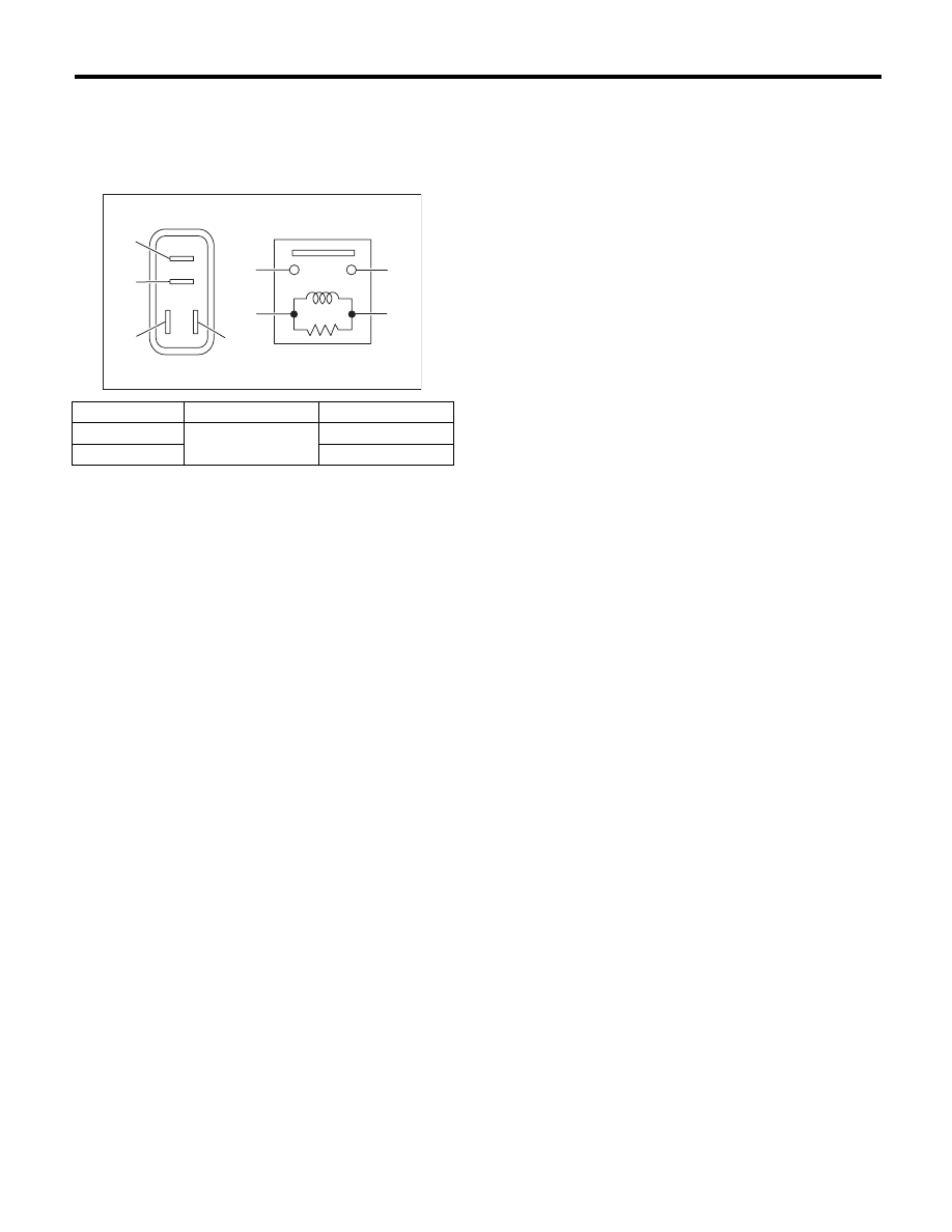
2. LOW BEAM RELAY
Measure the resistance between the daytime run-
ning relay terminals when connecting terminal No.
4 to the battery positive terminal and terminal No. 3
to the battery ground terminal.
Continuity
Terminal No.
Standard
Yes
1 and 2
Less than 1
:
No
1 M
: or more
LI-00001
(1)
(2)
(1)
(4)
(2)
(3)
(3)
(4)