Content .. 1046 1047 1048 1049 ..
Subaru Legacy IV (2008 year). Manual - part 1048
LI-9
Stop Light System
LIGHTING SYSTEM
7. Stop Light System
A: WIRING DIAGRAM
1. STOP LIGHT
<Ref. to WI-133, WIRING DIAGRAM, Stop Light
System.>
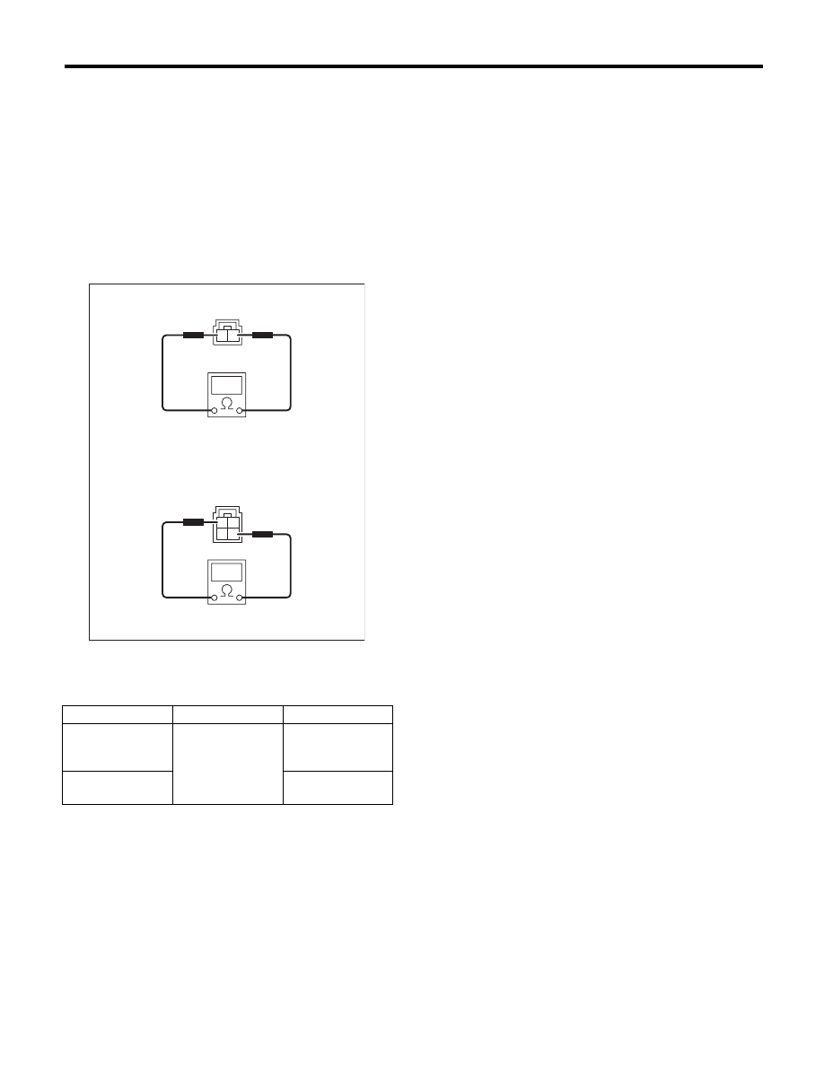
B: INSPECTION
1. STOP LIGHT SWITCH
Measure the resistance between stop light switch
terminals.
(1) Models without cruise control
(2) Models with cruise control
Switch position
Terminal No.
Standard
When brake pedal
is depressed
Models without
cruise control:
1 and 2
Less than 1
:
When brake pedal
is released
Models with cruise
control: 2 and 3
1 M
: or more
LI-00265
3
4
1
2
1
2
(1)
(2)