Subaru Legacy IV (2008 year). Manual - part 82


  Index      Subaru     Subaru Legacy IV - service repair manual 2008 year


Search            


Content   ..  80  81  82  83   ..


Subaru Legacy IV (2008 year). Manual - part 82


CO(H4SO)-14

Engine Coolant

COOLING

B: ADJUSTMENT

1. PROCEDURE TO ADJUST THE SUBARU SUPER COOLANT CONCENTRATION

CAUTION:
SUBARU Super Coolant concentration must be used from 50 to 60% to assure the best performance
of the anti-freeze and anti-rust agents.
To adjust the concentration of SUBARU Super Coolant according to temperature, find the proper SUBARU
Super Coolant concentration in the table, and add diluting water to the SUBARU Super Coolant (concentrat-
ed type) until it reaches the proper dilution.

Recommended Engine Coolant and Water for Dilution:

Refer to “SPECIFICATION” for the recommended engine coolant and diluting water. <Ref. to 
CO(H4SO)-2, SPECIFICATION, General Description.>

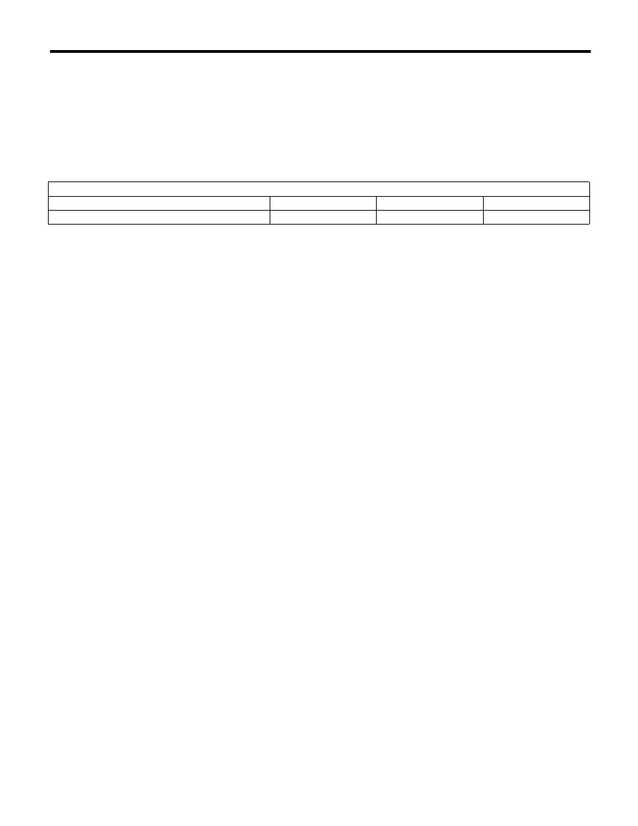
Relationship of SUBARU Super Coolant concentration and freezing temperature

SUBARU Super Coolant concentration

50%

55%

60%

Freezing temperature

–36°C (–33°F)

–41°C (–42°F)

–50°C (–58°F)

CO(H4SO)-15

Water Pump

COOLING

4. Water Pump

A: REMOVAL

1) Remove the radiator. <Ref. to CO(H4SO)-19,
REMOVAL, Radiator.>
2) Remove the V-belts. <Ref. to ME(H4SO)-38,
REMOVAL, V-belt.>
3) Remove the crank pulley. <Ref. to ME(H4SO)-
41, REMOVAL, Crank Pulley.>
4) Remove the timing belt cover. <Ref. to
ME(H4SO)-43, REMOVAL, Timing Belt Cover.>
5) Remove the timing belt. <Ref. to ME(H4SO)-44,
TIMING BELT, REMOVAL, Timing Belt.>
6) Remove the automatic belt tension adjuster.

7) Remove the camshaft position sensor. <Ref. to
FU(H4SO)-24, REMOVAL, Camshaft Position
Sensor.>
8) Remove the cam sprocket LH. <Ref. to
ME(H4SO)-49, REMOVAL, Cam Sprocket.>
9) Remove the belt cover No. 2 LH.

10) Remove the tensioner bracket.

11) Disconnect the hose from water pump.

12) Remove the water pump.

CO-00016

CO-00019

CO-00020

CO-00021

CO(H4SO)-16

Water Pump

COOLING

B: INSTALLATION

1) Install the water pump onto cylinder block LH.

NOTE:
• Use a new gasket.
• When installing the water pump, tighten the bolts
in two stages in alphabetical sequence as shown in
figure.

Tightening torque:

First

12 N·m (1.2 kgf-m, 8.9 ft-lb)

Second

12 N·m (1.2 kgf-m, 8.9 ft-lb)

2) Install the hose to water pump.
3) Install the tensioner bracket.

Tightening torque:

24.5 N·m (2.5 kgf-m, 18.1 ft-lb)

4) Install the belt cover No. 2 LH.

Tightening torque:

5 N·m (0.5 kgf-m, 3.7 ft-lb)

5) Install the cam sprocket LH. <Ref. to
ME(H4SO)-49, INSTALLATION, Cam Sprocket.>

6) Install the camshaft position sensor. <Ref. to
FU(H4SO)-24, INSTALLATION, Camshaft Position
Sensor.>
7) Install an automatic belt tension adjuster with the
tension rod held by a pin. <Ref. to ME(H4SO)-45,
AUTOMATIC BELT TENSION ADJUSTER AS-
SEMBLY AND BELT IDLER, INSTALLATION,
Timing Belt.>
8) Install the timing belt. <Ref. to ME(H4SO)-46,
TIMING BELT, INSTALLATION, Timing Belt.>
9) Install the timing belt cover. <Ref. to ME(H4SO)-
43, INSTALLATION, Timing Belt Cover.>
10) Install the crank pulley. <Ref. to ME(H4SO)-41,
INSTALLATION, Crank Pulley.>
11) Install the V-belts. <Ref. to ME(H4SO)-39, IN-
STALLATION, V-belt.>
12) Install the radiator. <Ref. to CO(H4SO)-20, IN-
STALLATION, Radiator.>

C: INSPECTION

1) Check the water pump bearing for smooth rota-
tion.
2) Check the water pump pulley for abnormalities.
3) Make sure the impeller is not abnormally de-
formed or damaged.
4) Inspect the clearance between impeller and
pump case.

Clearance between impeller and pump case:

Standard

0.5 — 1.5 mm (0.020 — 0.060 in)

5) After water pump installation, check pulley shaft
for engine coolant leaks or noise. If leaks or noise
are noted, replace the water pump assembly.

ME-02463

(F)

(E)

(D)

(C)

(B)

(A)

CO-00020

CO-00019

CO-00293

CO(H4SO)-17

Thermostat

COOLING

5. Thermostat

A: REMOVAL

1) Set the vehicle on a lift.
2) Lift up the vehicle.
3) Remove the under cover.
4) Drain engine coolant completely. <Ref. to
CO(H4SO)-13, DRAINING OF ENGINE COOL-
ANT, REPLACEMENT, Engine Coolant.>
5) Disconnect the radiator outlet hose from thermo-
stat cover.

6) Remove the thermostat cover, and then remove
the gasket and thermostat.

B: INSTALLATION

1) Install a gasket to thermostat.

NOTE:
Use a new gasket.
2) Install the thermostat and thermostat cover.

NOTE:
Install with the jiggle pin facing upward.

Tightening torque:

12 N·m (1.2 kgf-m, 8.9 ft-lb)

3) Connect the radiator outlet hose to thermostat
cover.
4) Install the under cover.
5) Lower the vehicle.
6) Fill engine coolant. <Ref. to CO(H4SO)-13,
FILLING OF ENGINE COOLANT, REPLACE-
MENT, Engine Coolant.>

(A) Thermostat cover

(B) Gasket

(C) Thermostat

CO-00270

CO-02336

(A)

(C)

(B)

(A) Thermostat cover

(B) Gasket

(C) Thermostat

(D) Jiggle pin

CO-02337

(A)

T

(B)

(C)

(D)


Content   ..  80  81  82  83   ..