Subaru Legacy IV (2008 year). Manual - part 80
CO(H4SO)-6
General Description
COOLING
D: PREPARATION TOOL
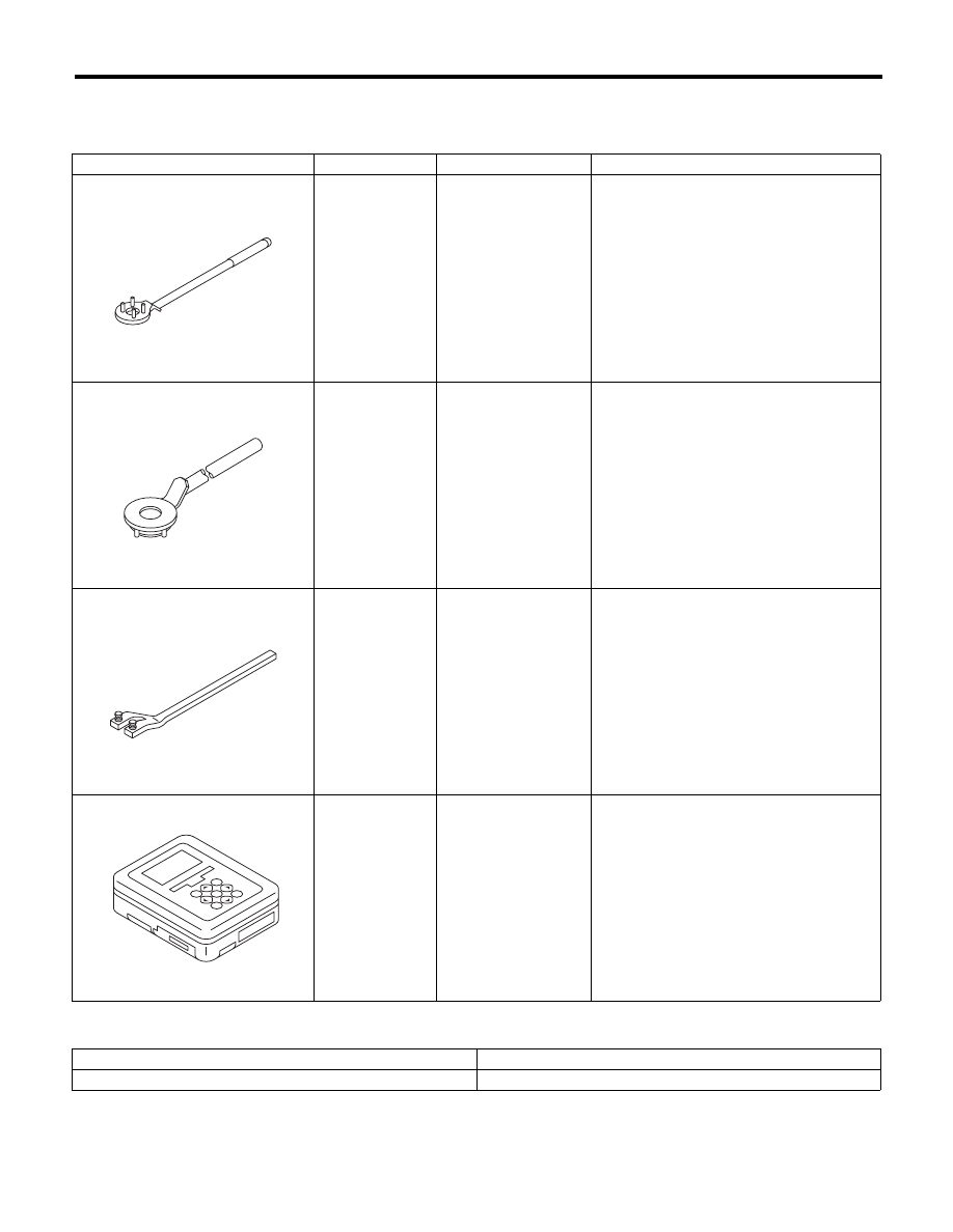
1. SPECIAL TOOL
2. GENERAL TOOL
ILLUSTRATION
TOOL NUMBER
DESCRIPTION
REMARKS
499977100
CRANK PULLEY
WRENCH
Used to stop rotation of the crank pulley
when loosening or tightening crank pulley
bolts. (MT model)
499977400
CRANK PULLEY
WRENCH
Used to stop rotation of the crank pulley
when loosening or tightening crank pulley
bolts. (AT model)
18231AA010
CAM SPROCKET
WRENCH
• Used for removing and installing cam
sprocket.
• CAM SPROCKET WRENCH (499207100)
can also be used.
1B022XU0
SUBARU SELECT
MONITOR III KIT
Used for troubleshooting the electrical sys-
tem.
TOOL NAME
REMARKS
Radiator cap tester
Used for checking radiator and radiator cap.
ST-499977100
ST-499977400
ST18231AA010
ST1B022XU0