Subaru Legacy IV (2008 year). Manual - part 39


  Index      Subaru     Subaru Legacy IV - service repair manual 2008 year


Search            


Content   ..  37  38  39  40   ..


Subaru Legacy IV (2008 year). Manual - part 39


FU(H4SO)-45

Fuel Tank

FUEL INJECTION (FUEL SYSTEMS)

22.Fuel Tank

A: REMOVAL

WARNING:
Place “NO OPEN FLAMES” signs near the
working area.

CAUTION:
Be careful not to spill fuel.
1) Set the vehicle on a lift.
2) Release the fuel pressure. <Ref. to FU(H4SO)-
43, RELEASING OF FUEL PRESSURE, PROCE-
DURE, Fuel.>
3) Drain fuel. <Ref. to FU(H4SO)-43, DRAINING
FUEL (WITH SUBARU SELECT MONITOR),
PROCEDURE, Fuel.>
4) Disconnect the ground cable from battery.

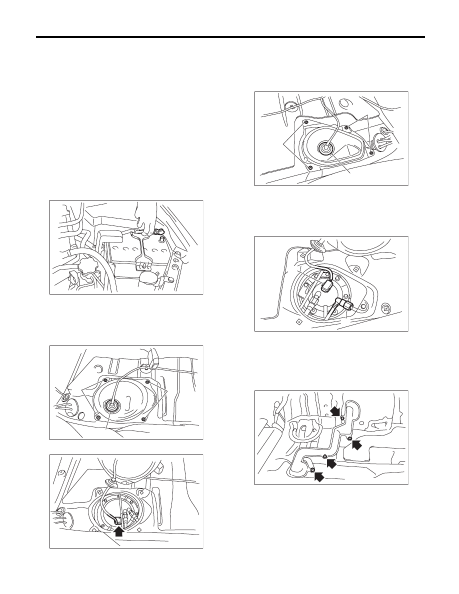
5) Remove the rear seat.
6) Remove the service hole cover of fuel pump.

(1) Remove the bolt (A).
(2) Push the grommet (B) down and remove the
service hole cover.

7) Disconnect the connector from fuel pump.

8) Remove the service hole cover of fuel sub level
sensor.

(1) Remove the bolt (A).
(2) Push the grommet (B) down and remove the
service hole cover.

9) Disconnect connector (A) from fuel sub level
sensor.
10) Disconnect the quick connector on the fuel de-
livery tube (B). <Ref. to FU(H4SO)-65, REMOVAL,
Fuel Delivery and Evaporation Lines.>

11) Remove the trunk room trim. (Sedan model)
<Ref. to EI-70, REMOVAL, Trunk Room Trim.>
12) Remove the rear quarter trim. (Wagon model)
<Ref. to EI-63, WAGON MODEL, REMOVAL, Rear
Quarter Trim.>
13) Remove the pipe protector.

IN-00203

FU-01124

(A)

(B)

(A)

FU-03989

FU-01126

(B)

(A)

(A)

FU-02830

(A)

(B)

FU-02390

FU(H4SO)-46

Fuel Tank

FUEL INJECTION (FUEL SYSTEMS)

14) Remove the grommet and disconnect the quick
connector of the evaporation pipe. <Ref. to
FU(H4SO)-65, REMOVAL, Fuel Delivery and
Evaporation Lines.>

15) Remove the rear wheels.
16) Lift up the vehicle.
17) Remove the bolts which secure the rear brake
hose mounting bracket.

18) Remove the rear disc brake assembly and tie it
to the body side of the vehicle.

19) Remove the parking brake cable from the park-
ing brake assembly. <Ref. to PB-6, REMOVAL,
Parking Brake Assembly (Rear Disc Brake).>
20) Remove the rear exhaust pipe. <Ref. to
EX(H4SO)-8, REMOVAL, Rear Exhaust Pipe.>
21) Remove the propeller shaft. <Ref. to DS-10,
REMOVAL, Propeller Shaft.>
22) Remove the heat shield cover and fuel tank
protector.

23) Disconnect the connector from the rear ABS
wheel speed sensor.

24) Remove the bolts securing the parking brake
cable clamp.

25) Remove the rear suspension assembly.

WARNING:
A helper is required to perform this work.

(1) Support the rear differential with the trans-
mission jack.
(2) Remove the bolts which hold the rear shock
absorber to the rear suspension arm.

FU-02391

FU-01128

FU-00462

FU-02894

FU-02895

FU-02896

FU-01132

FU(H4SO)-47

Fuel Tank

FUEL INJECTION (FUEL SYSTEMS)

(3) Remove the bolts which secure the rear
suspension assembly to the body.

(4) Remove the rear suspension assembly.

26) Disconnect the connector.

27) Disconnect the evaporation hose.

28) Disconnect the fuel filler hose (A) and evapora-
tion hose (B).

29) Support the fuel tank with a transmission jack,
remove the bolts from the fuel tank band, and re-
move the fuel tank from the vehicle.

WARNING:
• A helper is required to perform this work.
• Fuel may remain in the fuel tank. This will
cause the left and right sides to be unbalanced.
Be careful not to drop the fuel tank when re-
moving.

FU-01133

FU-02891

FU-02392

FU-02393

(A)

FU-02394

(B)

FU-03293

FU(H4SO)-48

Fuel Tank

FUEL INJECTION (FUEL SYSTEMS)

B: INSTALLATION

1) Support the fuel tank with a transmission jack,
set the fuel tank in place, and temporarily tighten
the bolts of the fuel tank band.

WARNING:
A helper is required to perform this work.

2) Securely insert the fuel filler hose (A) and evap-
oration hose (B) into the specified position, then at-
tach the clamp or clip as shown in the figure.

3) Connect the evaporation hose.

4) Tighten the fuel tank band bolts.

Tightening torque:

33 N·m (3.4 kgf-m, 24.3 ft-lb)

5) Connect the connector.

(1) Hose

(2) Clamp or clip

(3) Pipe

FU-03293

(A)

FU-02394

(B)

( 1 )

( 2 )

( 3 )

FU-00104

L

L/2

FU-02393

FU-02392


Content   ..  37  38  39  40   ..