Subaru Legacy IV (2008 year). Manual - part 37


  Index      Subaru     Subaru Legacy IV - service repair manual 2008 year


Search            


Content   ..  35  36  37  38   ..


Subaru Legacy IV (2008 year). Manual - part 37


FU(H4SO)-37

Rear Oxygen Sensor

FUEL INJECTION (FUEL SYSTEMS)

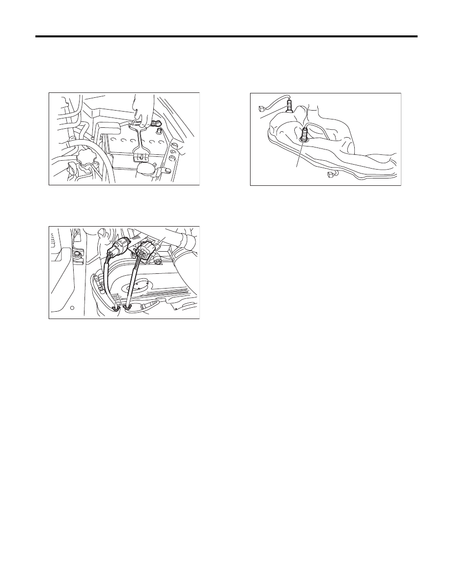
16.Rear Oxygen Sensor

A: REMOVAL

1) Set the vehicle on a lift.
2) Disconnect the ground cable from battery.

3) Remove the air intake duct. <Ref. to IN(H4SO)-
8, REMOVAL, Air Intake Duct.>
4) Remove the clip fastening the harness and dis-
connect the rear oxygen sensor connector.

5) Lift up the vehicle.
6) Remove the under cover.
7) Apply spray-type lubricant to the threaded por-
tion of rear oxygen sensor, and leave it for one
minute or more.

8) Remove the rear oxygen sensor.

CAUTION:
When removing the rear oxygen sensor, wait
until exhaust pipe cools, otherwise it will dam-
age the exhaust pipe.

(A) Front oxygen (A/F) sensor connector

(B) Rear oxygen sensor connector

(C) Clip

IN-00203

(C)

(B)

(A)

EX-02350

(A) Front oxygen (A/F) sensor

(B) Rear oxygen sensor

(A)

(B)

FU-02735

FU(H4SO)-38

Rear Oxygen Sensor

FUEL INJECTION (FUEL SYSTEMS)

B: INSTALLATION

CAUTION:
If lubricant is spilt onto the exhaust pipe, wipe it
off with cloth to avoid emission of smoke or
causing a fire.
1) Before installing rear oxygen sensor, apply the
anti-seize compound only to the threaded portion of
rear oxygen sensor to make the next removal eas-
ier.

CAUTION:
Never apply anti-seize compound to the protec-
tor of rear oxygen sensor.

Anti-seize compound:

NEVER-SEEZ NSN, JET LUBE SS-30 or 
equivalent

2) Install the rear oxygen sensor.

Tightening torque:

21 N·m (2.1 kgf-m, 15.5 ft-lb)

3) Install the under cover.
4) Lower the vehicle.
5) Connect the rear oxygen sensor connector and
fasten the harness with clips.

6) Connect the ground cable to battery.

(A) Front oxygen (A/F) sensor

(B) Rear oxygen sensor

(A) Front oxygen (A/F) sensor connector

(B) Rear oxygen sensor connector

(C) Clip

(A)

(B)

FU-02735

(C)

(B)

(A)

EX-02350

IN-00203

FU(H4SO)-39

Engine Control Module (ECM)

FUEL INJECTION (FUEL SYSTEMS)

17.Engine Control Module (ECM)

A: REMOVAL

1) Disconnect the ground cable from battery.

2) Remove the lower inner trim of passenger’s
side. <Ref. to EI-61, REMOVAL, Lower Inner
Trim.>
3) Detach the floor mat of passenger’s seat.
4) Remove the protect cover.

5) Remove the bolts and nuts which hold the ECM
to the bracket.

6) Disconnect the ECM connectors, and take out
the ECM.

B: INSTALLATION

Install in the reverse order of removal.

CAUTION:
When the ECM of model with immobilizer has
been replaced, be sure to perform the registra-
tion of immobilizer system. (Refer to the “PC
application help for Subaru Select Monitor”.)

NOTE:
When replacing the ECM, be careful not to use the
wrong spec. ECM to avoid any damage on the fuel
injection system.

Tightening torque:

7.5 N·m (0.8 kgf-m, 5.5 ft-lb)

IN-00203

FU-03416

FU-03417

FU(H4SO)-40

Main Relay

FUEL INJECTION (FUEL SYSTEMS)

18.Main Relay

A: REMOVAL

1) Disconnect the ground cable from battery.

2) Remove the glove box. <Ref. to EI-52, REMOV-
AL, Glove Box.>
3) Remove the harness cover (A).

4) Disconnect the connectors from main relay.

B: INSTALLATION

Install in the reverse order of removal.

IN-00203

FU-02092

(A)

FU-02093


Content   ..  35  36  37  38   ..