Subaru Legacy IV (2008 year). Manual - part 36
FU(H4SO)-33
Variable Valve Lift Diagnosis Oil Pressure Switch
FUEL INJECTION (FUEL SYSTEMS)
13.Variable Valve Lift Diagnosis
Oil Pressure Switch
A: REMOVAL
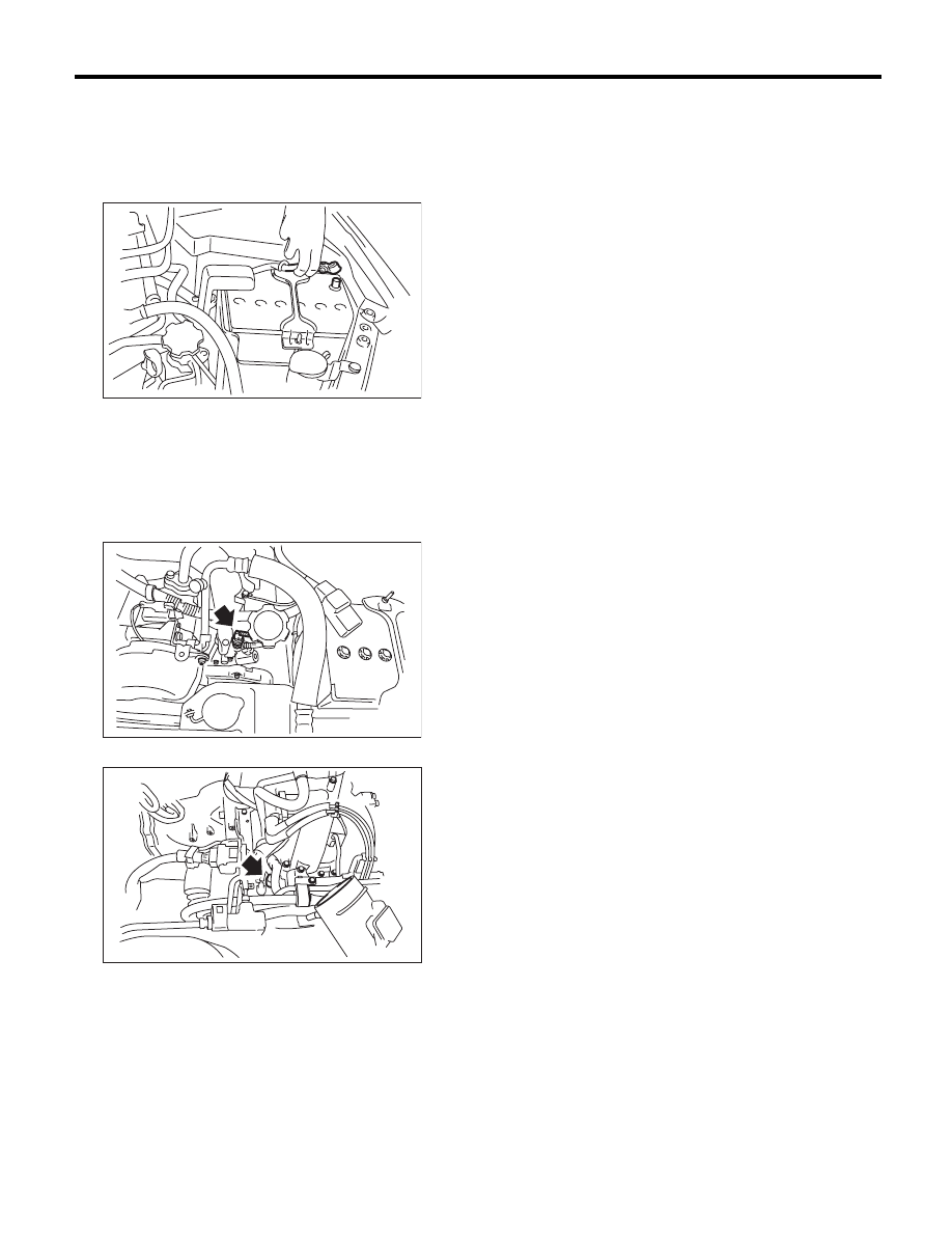
1) Disconnect the ground cable from battery.
2) Remove the air intake chamber. <Ref. to
IN(H4SO)-7, REMOVAL, Air Intake Chamber.>
3) Disconnect the connector from the variable
valve lift diagnosis oil pressure switch.
4) Remove the variable valve lift diagnosis oil pres-
sure switch.
• LH side
• RH side
B: INSTALLATION
Install in the reverse order of removal.
NOTE:
Apply liquid gasket to the variable valve lift diagno-
sis oil pressure switch threads.
Liquid gasket:
THREE BOND 1324 (Part No. 004403042) or
equivalent
Tightening torque:
17 N·m (1.7 kgf-m, 12.5 ft-lb)
IN-00203
FU-02731
FU-02732